I’ve been interested in making some nice electronic music and sound effects for my games. I tend to find the UI of different VSTs frustrating, so I was interested in getting a MIDI controller that could help speed things up. I’m also interested in the possibilities of rigging the MIDI knobs to variables in the code so I could tweak different parameters in real time. Like any good (over-)engineer, I researched what it might take to put one together myself. For whatever reason I find this sort of controller hardware fascinating.
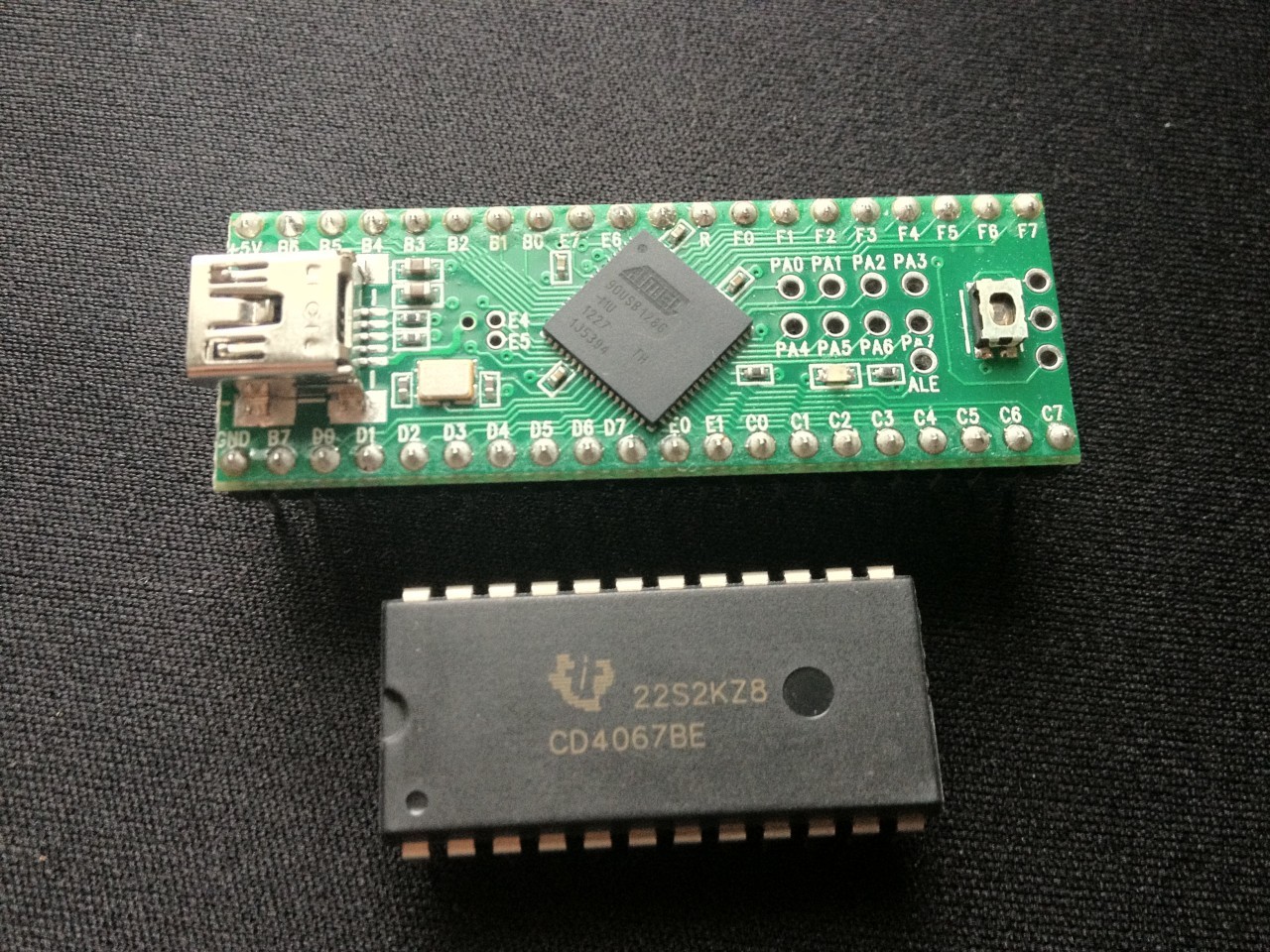
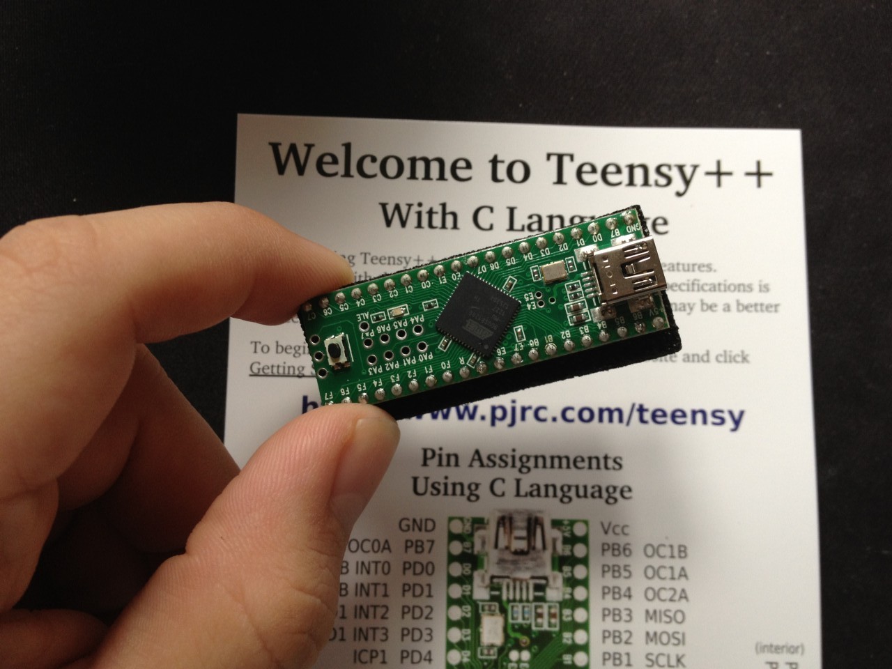
First I had to find a good micro controller. I have about 5 Arduino’s lying around the house, but I also discovered (while working on an arcade cabinet for PIGSquad that the Arduino USB controller can’t easily be reprogrammed to behave as a game pad or MIDI device; instead it always identifies itself as a serial device. There’s software to convert serial to MIDI, but I wanted to go a more user friendly approach. My search led me to an awesome controller called Teensy. It’s even local to me in Oregon! Teensy can be programmed using both C++ or the Arduino IDE, including most of the Arduino libraries. It supports flashing the USB controller as an HID (human interface device such as a mouse or keyboard), joypad or even MIDI device. It’s smaller, cheaper, and has more ports than the Arduino (I got the Teensy++ 2.0). I love this thing!
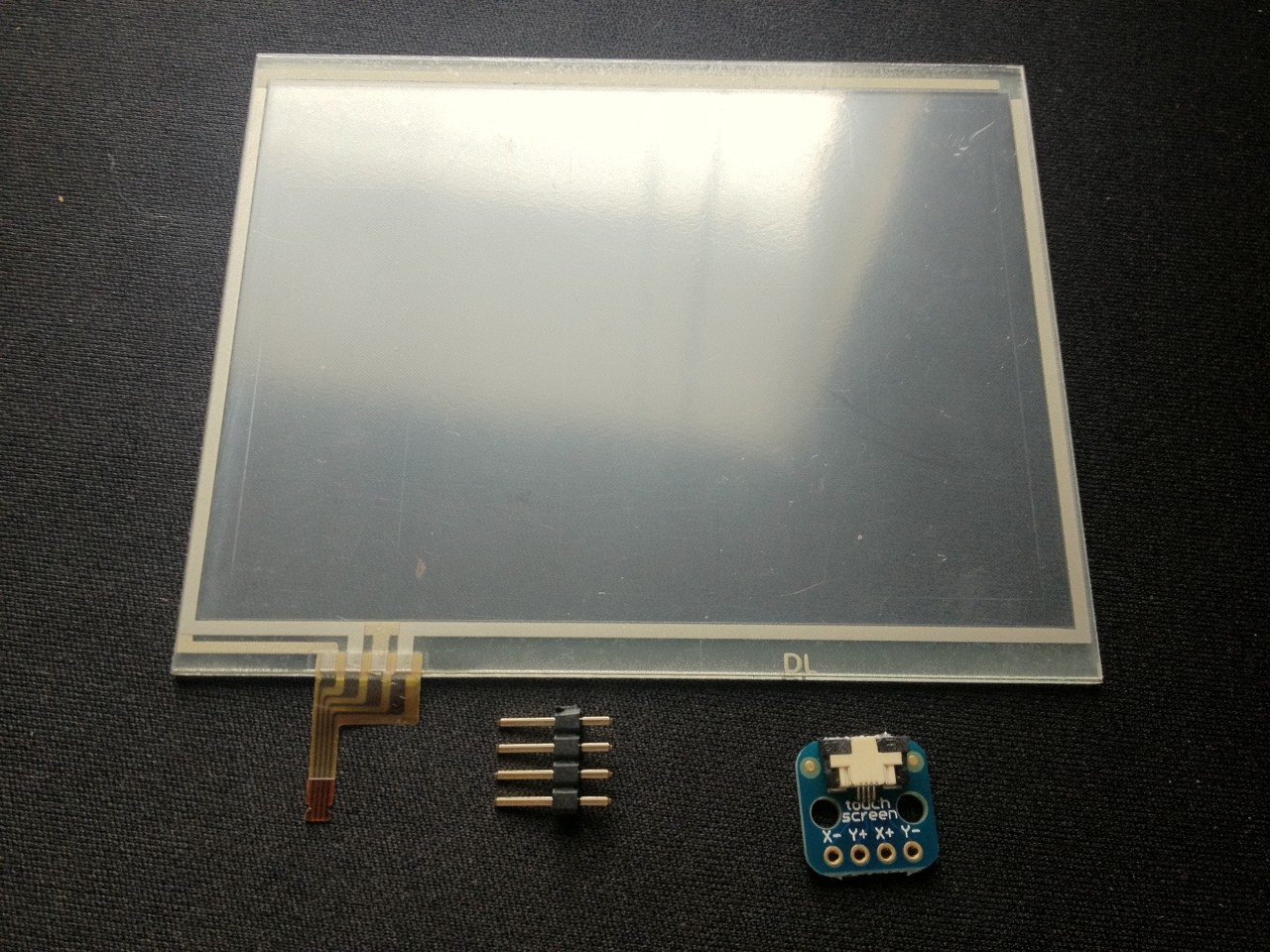
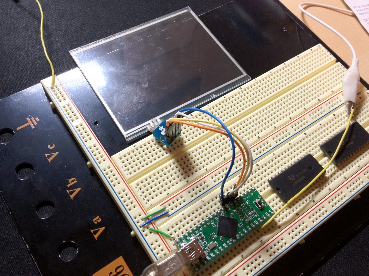
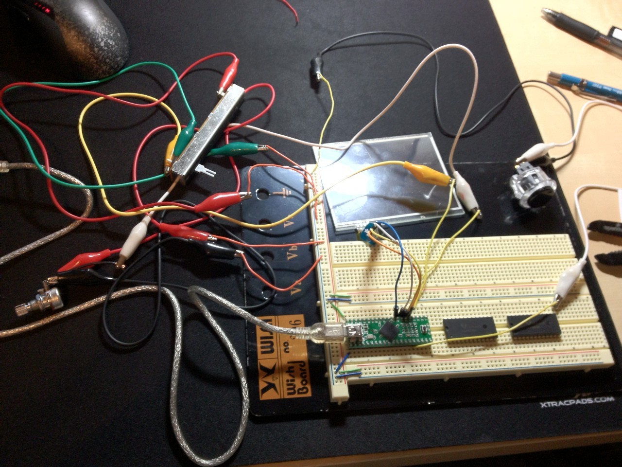
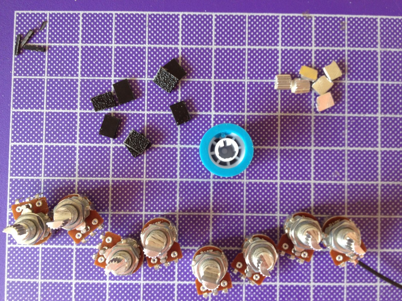
I wanted to test out a few interface options so I got my hands on some sliding and rotary potentiometers from SparkFun, some Sanwa arcade buttons, and for a bonus unique feature a Nintendo DS XL touchscreen. I hooked them all up in a test circuit to make sure I could wire them to the Teensy as I expected. I was able to use the excellent Instructable from Fuzzy-Wobble to source most of the parts and a nice testing sketch for the Teensy. I strongly recommend this tutorial if you’re interested in putting something like this MIDI controller together. Also if you want to make a custom controller but you’re not so interested in the circuit design aspect, Fuzzy-Wobble (Alex) has an incredibly cool looking product called the Teensy Monster. I haven’t played with it, but it has some great features and I really appreciate the openness of the system; it definitely seems worth supporting.
The touchscreen (a Nintendo DS “digitizer” if you’re going to search for it) I grabbed off of Amazon for just a few dollars. The breakout board for the ribbon and the Arduino library for reading the touchscreen data and debouncing was provided by the always excellent Adafruit. After wiring it up on a breadboard and loading some code onto Teensy, I was in business.
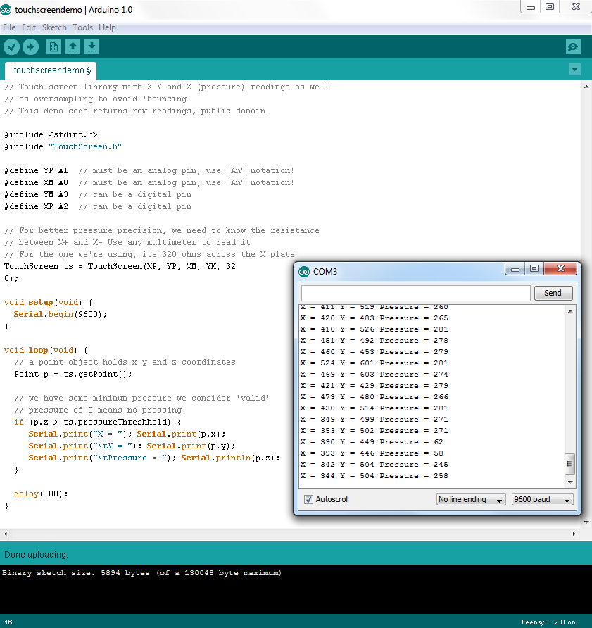
// Uses touchscreen library from adafruit and largely inspired by fuzzywobble

#include
#include "TouchScreen.h"

//TOUCHSCREEN
#define YP A1  // must be an analog pin, use "An" notation!
#define XM A0  // must be an analog pin, use "An" notation!
#define YM A3  // can be a digital pin
#define XP A2  // can be a digital pin

// For better pressure precision, we need to know the resistance
// between X+ and X- Use any multimeter to read it
// For the one we're using, its 320 ohms across the X plate
TouchScreen touchscreen = TouchScreen(XP, YP, XM, YM, 320);

//PUSHBUTTONS
//pin assignment below
int button_pin = 13;

//POTENTIOMETER
//potentiomer variables defined below
int pot_pin = A4; //potentiometer is hooked up to pin analog 4 (f4) on the Teensy++
int pot_value = ;
int pot_value_old = ;

//SLIDER
int slider_pin = A5; //slider is hooked up to pin analog 5 (f5) on the Teensy++
int slider_value = ;
int slider_value_old = ;

//LED
//pin assignment below
int led_pin = 6; //led is hooked up to digital pin 6 on the Teensy++ 2.0


void setup()
{
  //begin serial communication at 9600bps
  //this allows the arduino to talk to the computer (serial monitor)
  Serial.begin(9600);

  //PUSHBUTTONS
  //declare that pushbutton pins are inputs and turn on pullup resistor
  pinMode(button_pin, INPUT_PULLUP);
}

void loop()
{ //this loops over and over and over forever while the Teensy++ is powered

   //PUSHBUTTON
   if (digitalRead(button_pin) == LOW)
   { // button was pushed
     Serial.println("Button Pressed");
     digitalWrite(led_pin, HIGH);
     delay(250);
     analogWrite(led_pin, LOW);
   }

   //POTENTIOMETER
   // range 0-1024
   pot_value = analogRead(pot_pin);
   if (abs(pot_value_old - pot_value) > 5)
   { //check if analog value changed from the last reading with a (high) threshold of 5
     Serial.print("Potentiometer Value: ");
     Serial.println(pot_value); //write the value to the serial monitor
     pot_value_old = pot_value; //reset the current value
     delay(250);
   }

   //SLIDER
   // range 0-1024
   slider_value = analogRead(slider_pin);
   if (abs(slider_value_old - slider_value) > 5)
   { //check if analog value changed from the last reading with a (high) threshold of 5
     Serial.print("Slider Value: ");
     Serial.println(slider_value); //write the value to the serial monitor
     slider_value_old = slider_value; //reset the current value
     delay(250);
   }

  //TOUCHSCREEN
  // x range 100-900
  // y range 100-900
  // pressure range 400(low) - 50(high)
  // a point object holds x y and z coordinates
  Point p = touchscreen.getPoint();
  // we have some minimum pressure we consider 'valid'
  // pressure of 0 means no pressing!
  if (p.z > touchscreen.pressureThreshhold) {
     Serial.print("X = "); Serial.print(p.x);
     Serial.print("\tY = "); Serial.print(p.y);
     Serial.print("\tPressure = "); Serial.println(p.z);
     delay(250);
  }
}
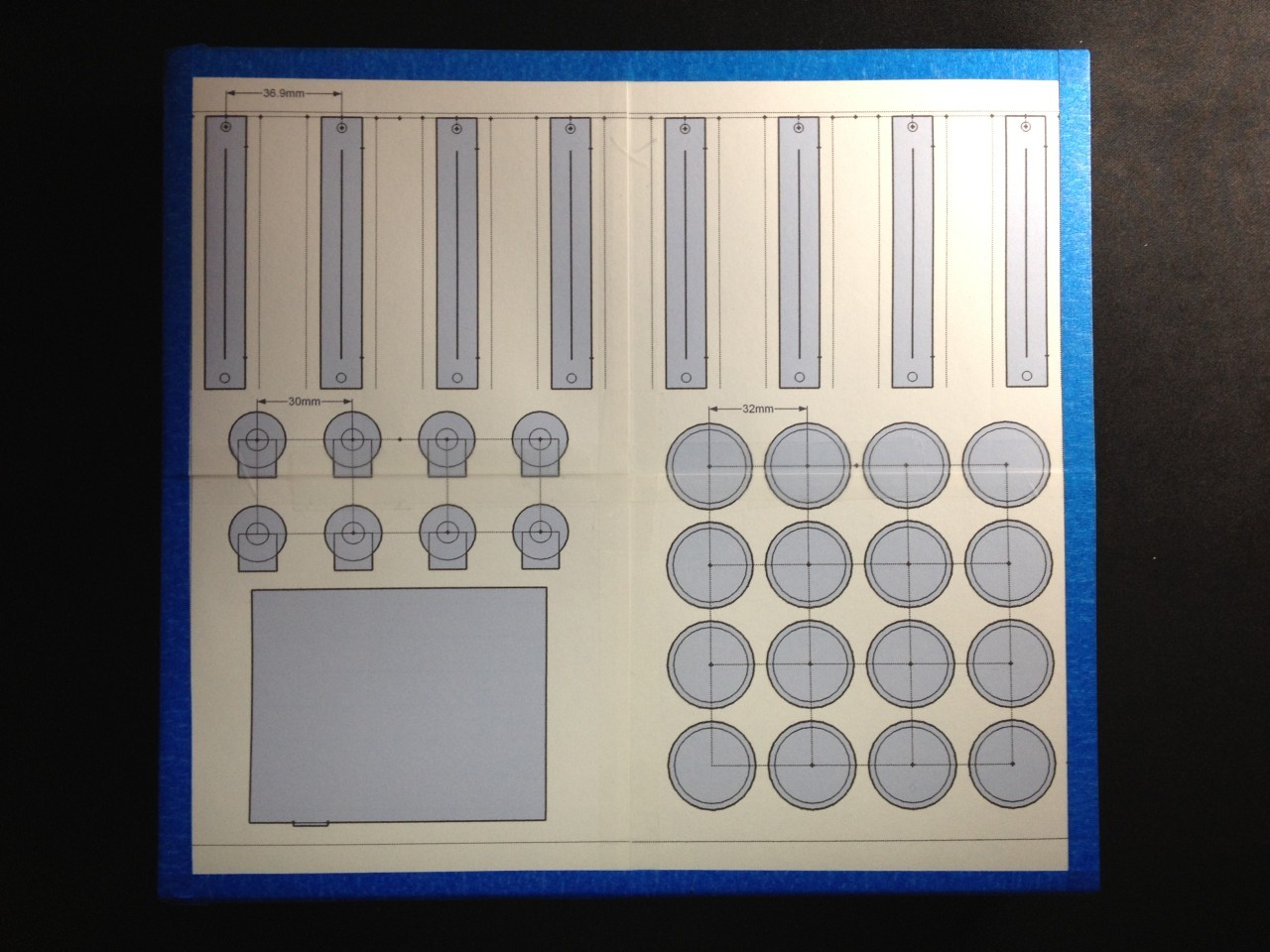
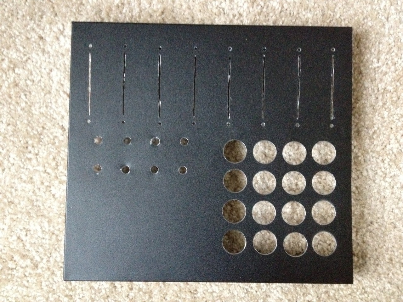
After I got the circuit built and the hardware tested, I was ready to design the physical controller. I knew I wanted a 4x4 grid of buttons so they could be compatible with the sample packs provided for the MidiFighter from DJ TechTools. The folks behind DJ TechTools have also posted a number of handy videos on building your own custom MIDI controller. They also sell the Sanwa arcade buttons and the colorful potentiometer knobs that I’m using in this project. If you like the look of this controller but you’re not too keen on building one yourself, definitely check out their site!
The hardest part of building the controller so far has definitely been sourcing a nice project box to house everything. I spent several hours looking online for a good metal project box that met my dimensions, but everything was too small or too expensive. I was hoping for a workspace roughly 12 inches wide. Then I took a trip to my local gadget store Surplus Gizmos and found the perfect case. For $10 I got a roughly 11”;x12”; stainless steel with black powder coating case, with rubber feet and vents.
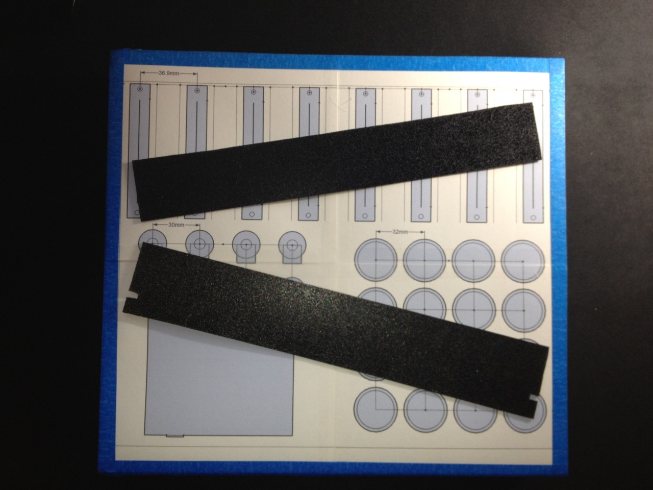
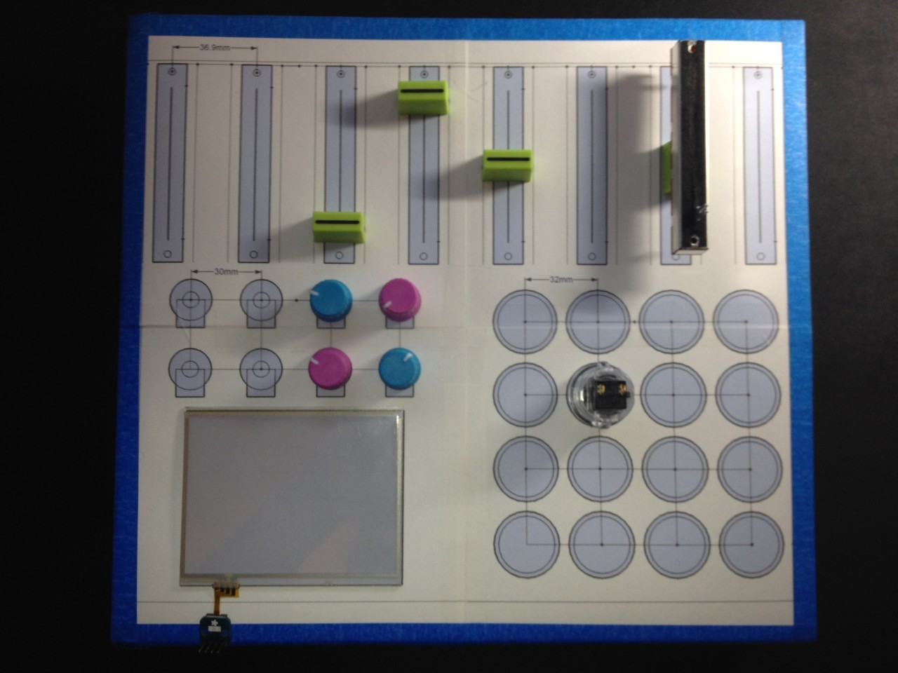
With the case sourced, I could start laying out the remaining parts. I have never used any CAD tools for this kind of design, and thought the quickest way to make the layout would in be SketchUp. After a night of measuring, reading tech specs and learning my way around SketchUp, I came up with the following layout:

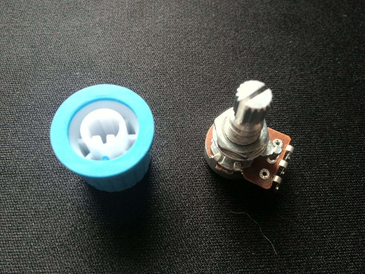
In order to make a tight fit with the arcade buttons so they didn’t twist, I used a scrap piece of plastic drilled in the same pattern as the case to add some thickness for the clips on the buttons. I also used the same plastic for the rotary potentiometers. Because the potentiometers are meant to be mounted in a stationary position (so only the knob twists), they have a 1mm tall peg that can be fastened into the mounting surface. I used the extra plastic to make holes for the pegs, and then mounted that to the case. Unfortunately the rotary potentiometers I got from SparkFun are knurled (meaning they shaft is slotted) to allow the knobs to stay on securely. Unfortunately, the knobs I ordered are for D-shaft potentiometers, which won’t fit on the knurled shaft. After a little fudging, I was able to cut off half of the knob with my Dremel and add some plastic scraps to make the shaft a snug fit for the knobs.
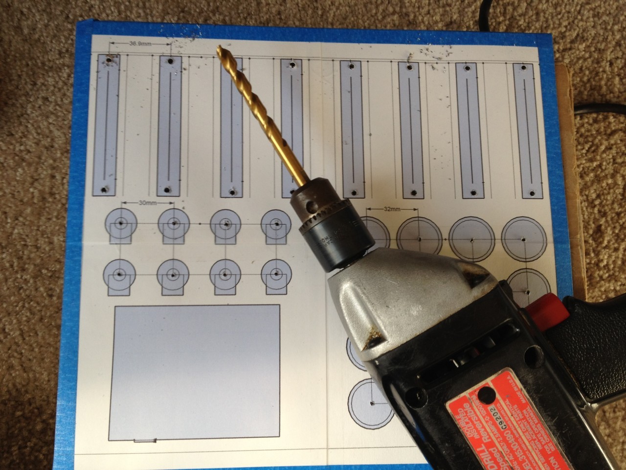
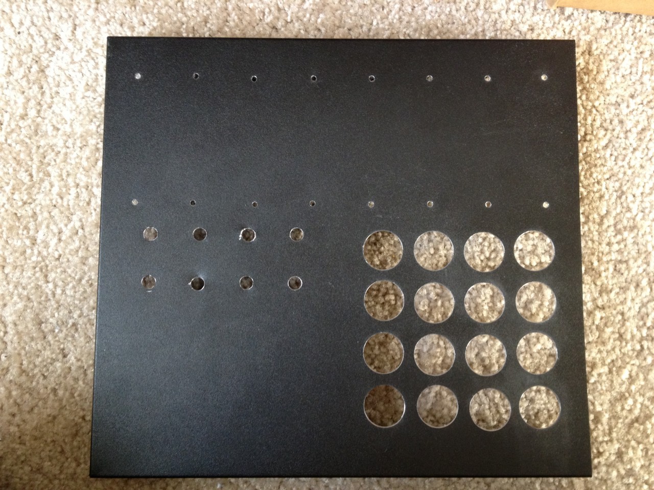
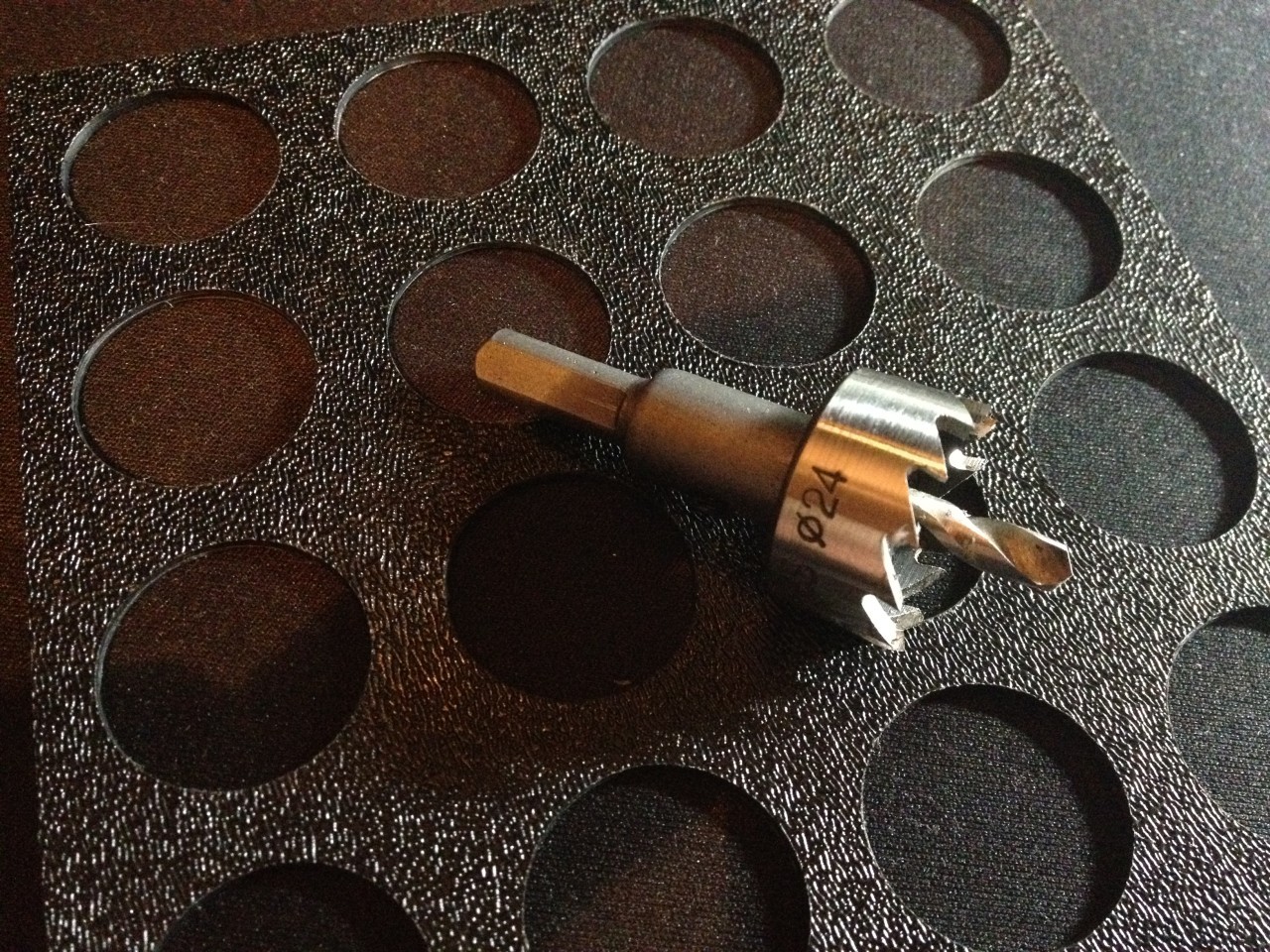
I wanted to have a precise layout, and considered sending the case off for laser or water-jet cutting, but decided it would be prohibitively expensive. Instead I purchased a hole saw specifically for the size of the arcade buttons for a few dollars, and the rest I was able to do with a dremel. My biggest concern was cutting the straight lines for the sliders. They turned out alright, and after some filing the sliders are able to move smoothly. A little paint could finish cleaning up the lines, which can be polished up later.
With the shell put together I still have a lot of work ahead of me wiring and soldering together the circuit, and finally mapping the controls to the DAW on the computer. The touchscreen needs to be fastened to the surface and I haven’t decided how to produce a professional looking molding around the edges. I also have some extra features in store, such as adding LEDs to the buttons so they light up when pressed. There is some more planning that needs to be done as well to make sure the controller doesn’t overdraw power from the USB port. But we’ll save that for another update!