I recently built a DZ65RGB keyboard to replace my TADA68 and I’ve been thrilled with it, but it is lacking one major feature: it has no underglow support. So I undertook a challenge to add high quality LEDs to the underside of my favorite TADA68 case, powered through the DZ65RGB PCB, and controlled by the keyboard microcontroller (an STM32 ARM Cortex) running the QMK firmware. While underglow is a configuration setting in QMK for many AVR microcontrollers, it is not supported out of the box for the STM32 ARM microcontroller, and it conflicts with the individually addressable RGB LEDs. This is a detailed tutorial on the hardware and software required to enable additional dimmable lights to any STM32 keyboard with full production-quality integration.
Getting Started
I have a lofty goal of replacing or improving the LED functionality of the TADA68, with an extremely high quality integration. This means a number of single color, non-addressable LEDs, with dimming capability, and the appropriate keycodes to control the lights with hotkeys. Let me break down all the pieces that need to be solved so we can tackle them one at a time:
How to Control the LEDs
We know we want to control the LEDs with QMK, and this isn’t the sort of thing that can simply be “configured” with user-facing QMK tools. We need to be able to build QMK from source, and add new functionality to these extra pins on the keyboard. Particularly because we’re tapping into pins that are not already configured in QMK, and because QMK lacks some support for backlight/underglow on STM32 ARM microcontrollers, and because we need to work around the conflicts with RGB LED backlights and LED underlights, we need to write some code for QMK to initialize and control the pins appropriately.
How to Address the LEDs
Although these pins are labeled on the PCB, we can’t be sure the labels map to the same pin names within QMK. Moreover, for advanced features such as making the LEDs dimmable, we need to know how to enable PWM on these pins. This will require identifying the microcontroller, finding the spec sheet, and understanding the available functionality for these pins.
How to Wire the LEDs
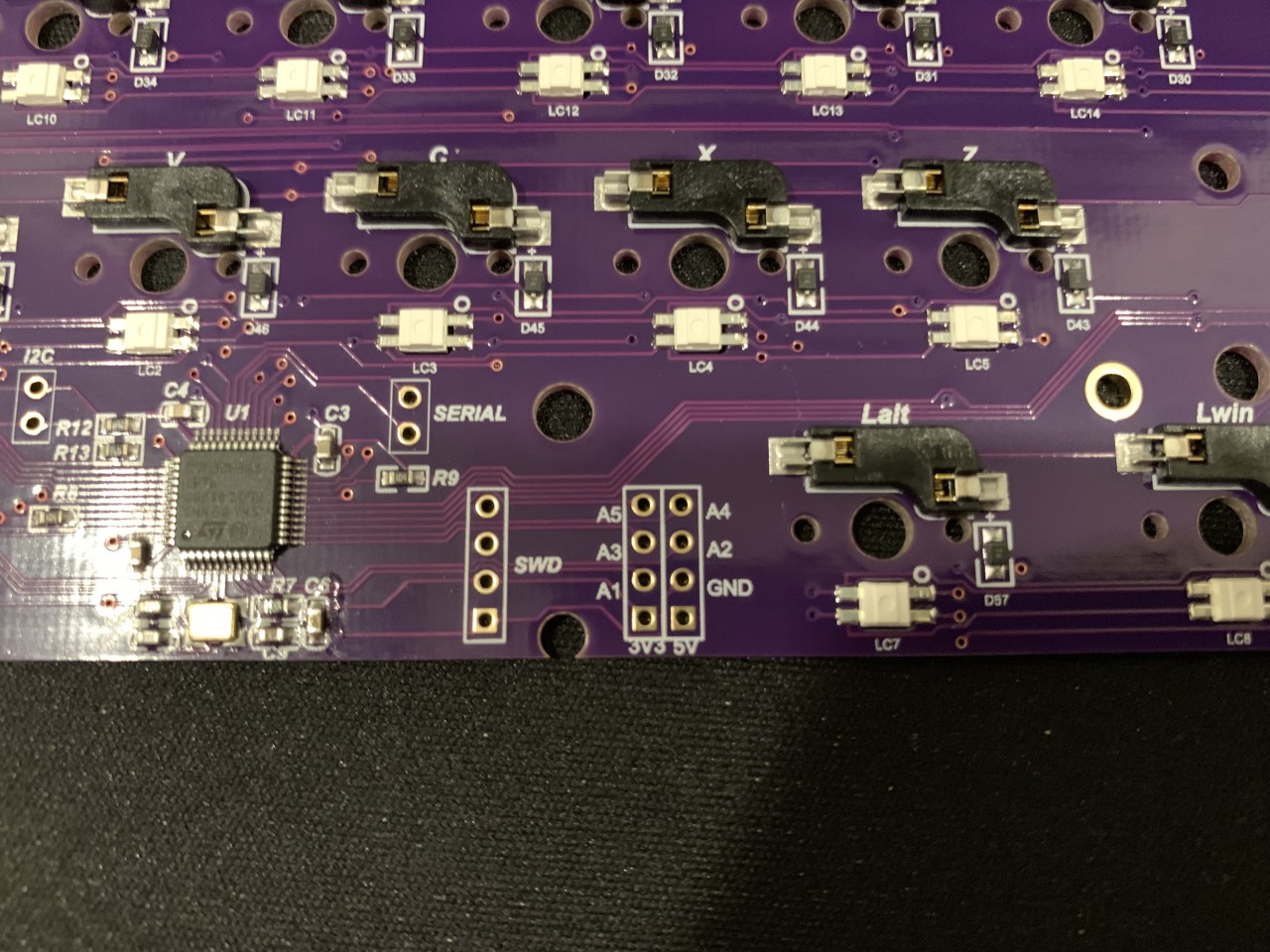
I know at a minimum I need the LEDs to draw power from the DZ65RGB PCB. This would be very straight forward, and simply requires tapping into the power lines on the USB port and adding the appropriate resistors for the LED voltage. However the real goal is to control the behavior of the LEDs using QMK, which means I would need to find an appropriate pin on the microcontroller to tap into. Upon inspecting the PCB, I found that there are several pins broken out on the PCB that don’t seem to have a use on the DZ65RGB. Let’s see if we can use one of those.
How to Mount the LEDs
The TADA68 has 4 white LEDs pointing down towards the desk, 2 on the left and 2 on the right side of the keyboard. There are holes in the case to allow light out. The DZ65RGB does not have these LEDs, most likely because the footprint for each switch on the PCB is much larger, and the RGB LED backlights are physically in the way of where the underglow LEDs were mounted on the TADA68. Fortunately because the holes already exist in the case, it is easier to devise a physical mounting location - LEDs can be packaged small enough to fit easily in the case and they can be glued into place, or an appropriate strip light can be mounted in a notch outside of the case.
Building QMK
Setting up the Environment
First, you can follow the Getting Started Guide to setup an environment that can build QMK. I’m running Windows 10, so per the instructions I had to install msys2 to create the build environment. I chose to install the 64 bit version.
When setting up the environment, clone the correct repository for your board. In the case of my DZ65RGB PCB, DZtech maintains a repository. But most keyboards are also available in the official QMK Firmware GitHub, which is what I ultimately used.
From the directory where I synced the DZTech QMK repository, running in MinGW (installed by MSYS) I ran util/qmk_install.sh and agreed to install all packages. It then asked which USB drivers to install, and I recommend pressing A to install all supported drivers. I originally connected my DZ65RGB board and chose C to install drivers for all connected keyboards, but I could not tell if this detected or installed anything for the DZ65RGB board and I think it may have caused me trouble down the line. I then agreed to install the AVR tool chain, which may not be necessary but I may program AVR boards in the future. Then I agreed to install the ARM tool chain, which certainly is needed. Finally, I agreed to add the qmk script to the end of my MSYS bash file and restarted MSYS.
I also received the error message WARNING: Some git sub-modules are out of date or modified, please consider running: make git-submodule the first time I tried to compile. This is very straightforward, just run make git-submodule. This will initialize the necessary git submodules.
Compiling QMK
Finally after the environment was set up, I was able to build the firmware using make dztech/dz65rgb:default which appeared to complete successfully. If you end up in a bad state (which happened to me occasionally), you can always start a build fresh after running make clean, and you can do a full rebuild by adding clean to the end of the build command, e.g. make dztech/dz65rgb:default clean
Flashing the Firmware
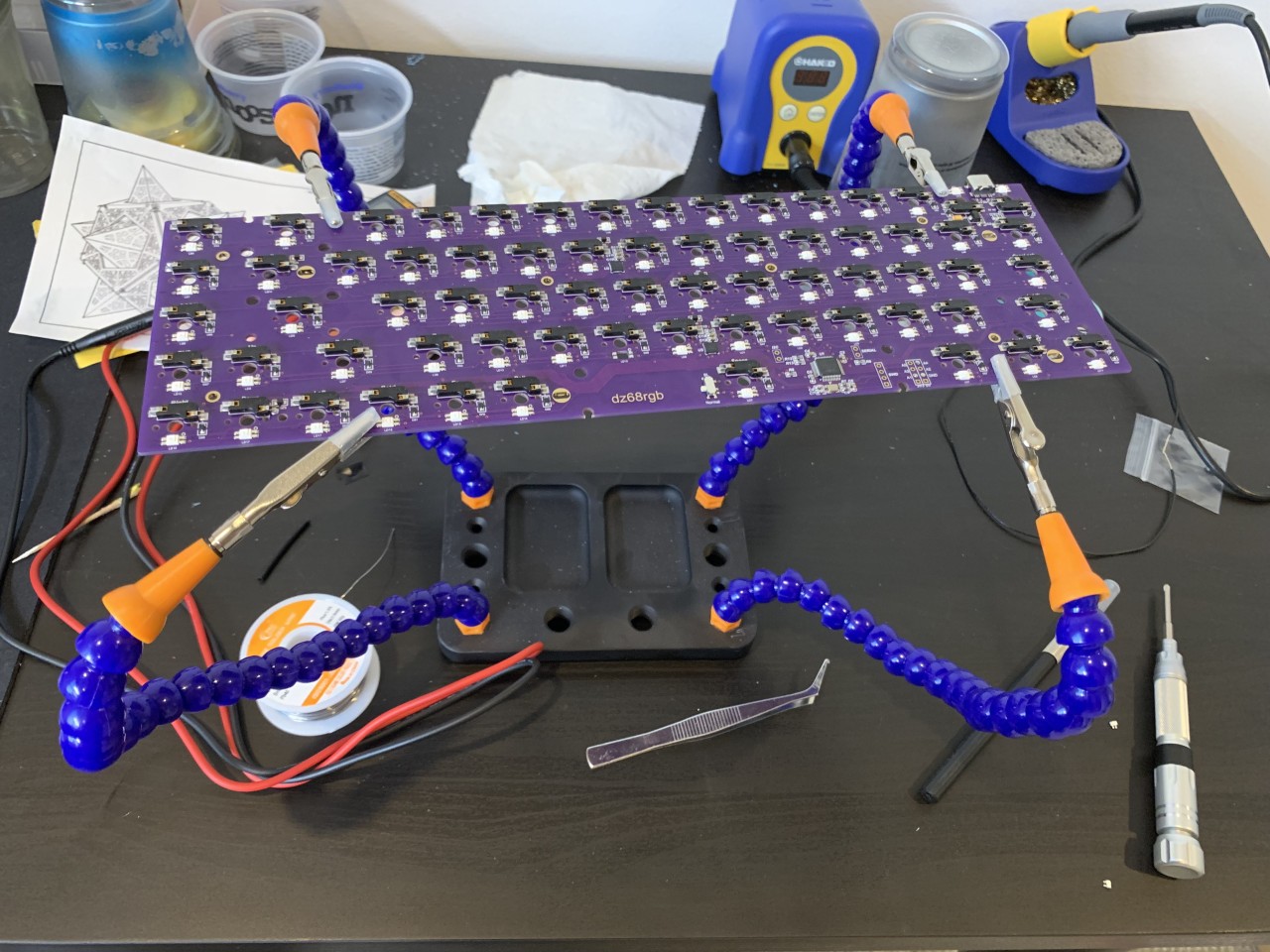
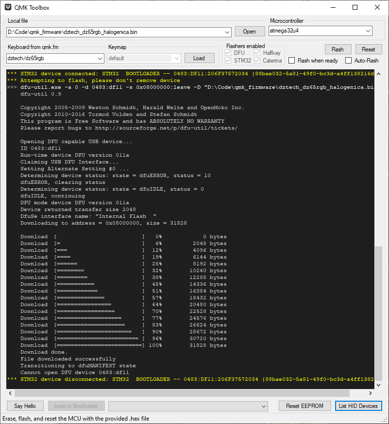
To make sure everything worked correctly, I flashed the keyboard with the new firmware I built and verified that keys were working as expected. I put my keyboard in the bootloader mode by holding ESC while plugging the USB in. To make firmware installation easy, QMK develops a tool called QMK Toolbox. I installed the portable version 0.0.10, and unfortunately it was incorrectly flagged as a trojan by windows defender, so I had to specifically allow this file in windows defender. After installing the toolbox, I received an error stating No DFU capable USB device available…
The kbdfans site instructs you to install the WinUSB driver via Zadig (I have version WinUSB (v6.1.7600.16385)). To do this, run Zadig, select the Options menu, and be sure to choose List All Devices. Select the STM32 BOOTLOADER from the dropdown (this may only be visible when the device is connected in the bootloader mode as described above). Then select the WinUSB driver, and choose Replace Driver. This is what was required to fix the No DFU... error. Once I reloaded the QMK Toolbox, I saw a notification that my keyboard was detected in the output window, which read STM32 device connected: STM Device in DFU Mode. I was able to open my firmware (...\qmk_firmware\dztech_dz65rgb_default.bin in my case) and press Flash - you can safely ignore the other dropdowns and buttons. After pressing Flash, QMK Toolbox should upload your firmware onto the DZ65RGB and the PCB will reboot with the RGB LEDs shifting through the colors of the rainbow. Congratulations on getting this far!
Simple Underglow
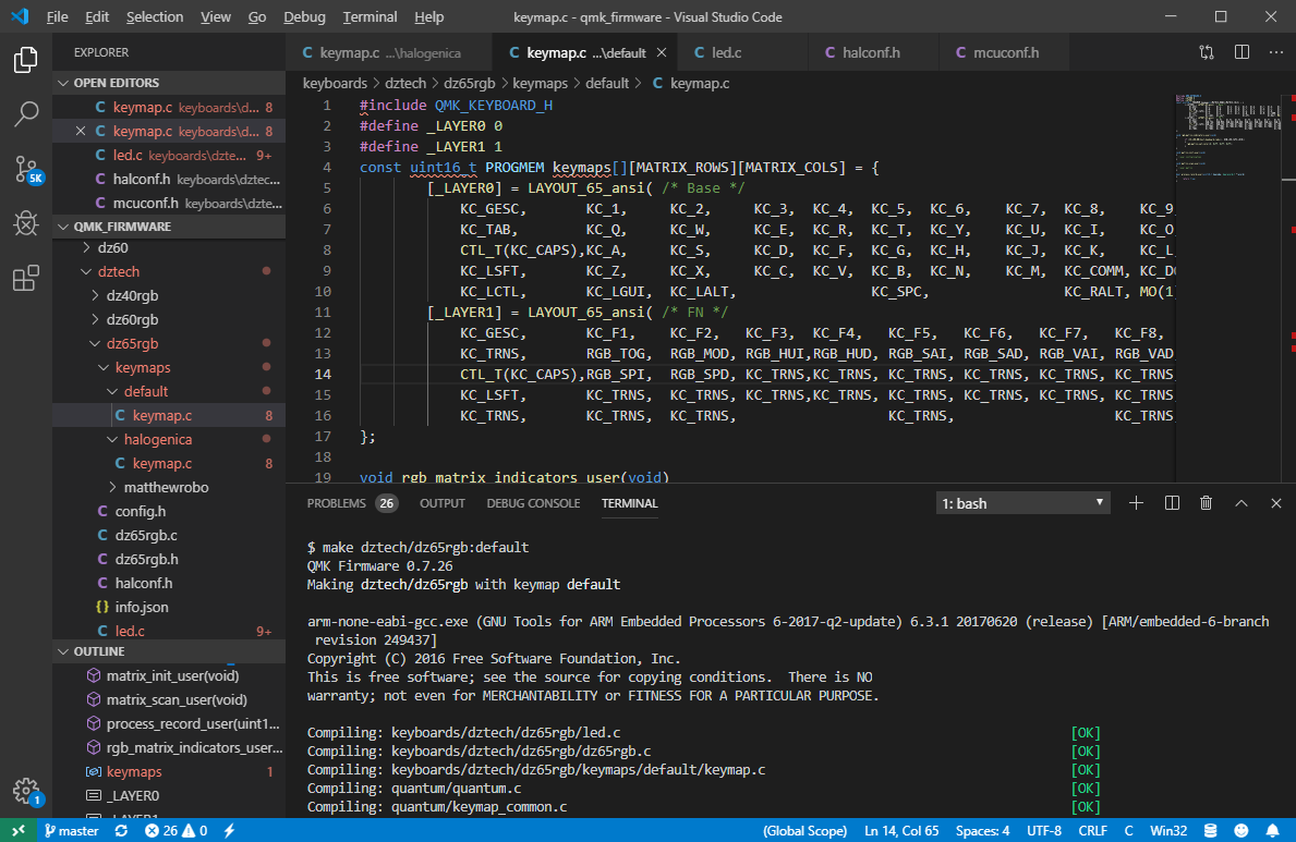
Now, let’s add underglow support. This is where things get a little tricky. The QMK firmware normally supports underglow via the RGBLIGHT feature. However, there are two downsides to this feature with the DZ65RGB: the function keys controlling the RGB lights conflict with the RGB_MATRIX feature, and the TADA68 case I’m dropping this board into typically has only 4 white underglow lights so I don’t plan on using RGB LEDs. Instead, I will be using single color LEDs, and control them with the BACKLIGHT feature, which will work great for LEDs of a single color, and will have unique function keys to control the LEDs. My understanding is this is not what the Backlight feature was intended for, but it should work, and avoid the conflicts with the RGB_MATRIX! In the ...\qmk_firmware\keyboards\dztech\dz65rgb\rules.mk file I enabled the BACKLIGHT feature by modifying the line BACKLIGHT_ENABLE = yes.
Identify the Microcontroller
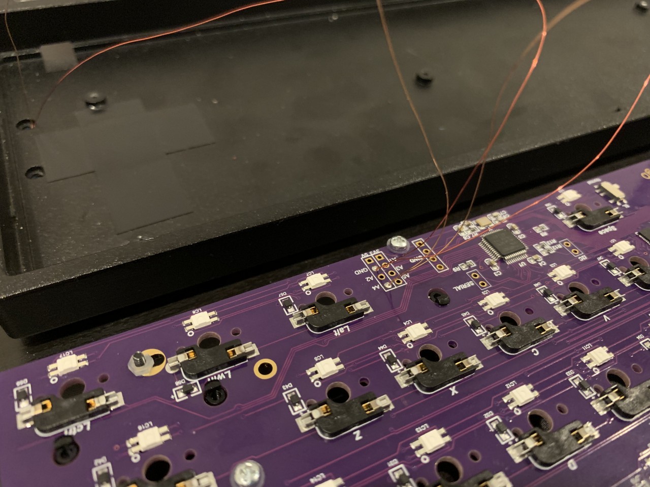
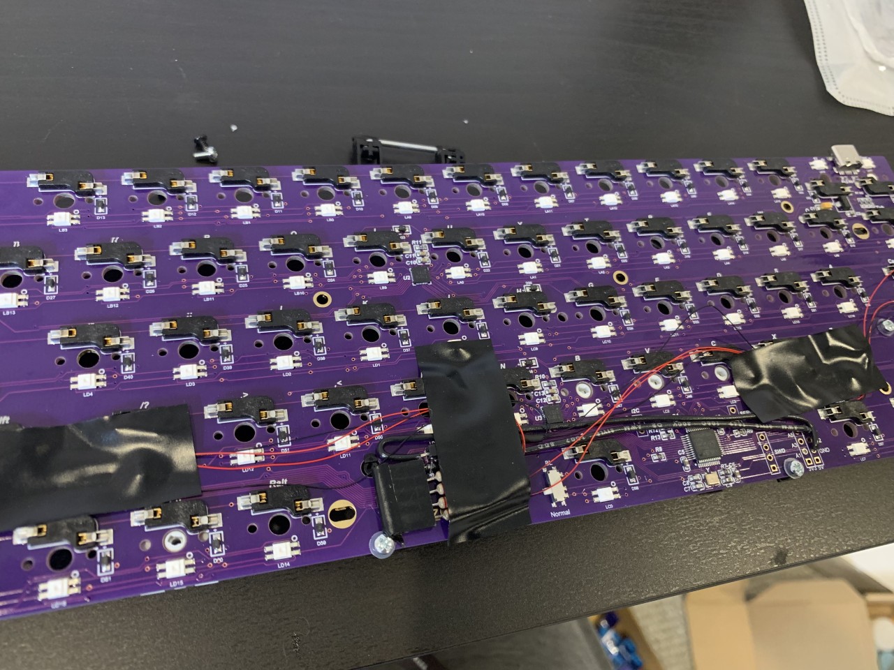
Up to this point I’ve mentioned the DZ65RGB uses an ARM chip, but I didn’t find this documented anywhere. Instead I had carefully inspect the PCB and take some very close up pictures to identify the microcontroller. This is also how I identified the breakout pins and followed the traces to pins A1, A2, A3, A4, and A5. I was able to read the chip and found the type of microcontroller: the STM32F303.
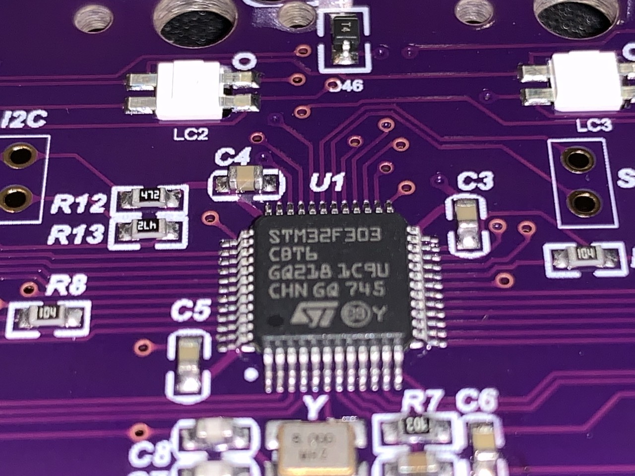
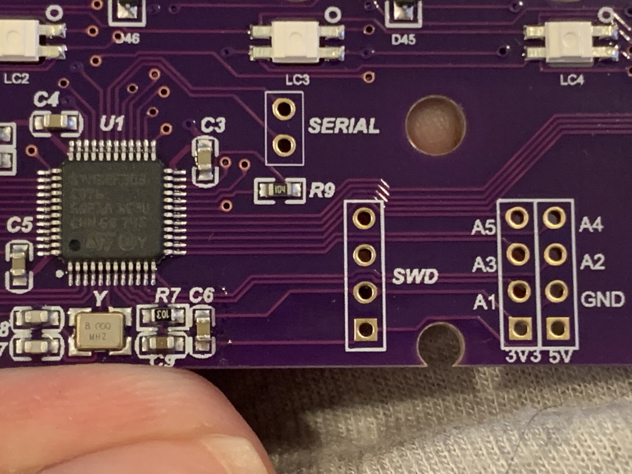
I was then able to find the spec sheet for the microcontroller, which was crucial to understand for this mod. I cross referenced it and found (on page 32) that the pinout labels on the PCB indeed lines up with PA1, PA2, PA3, PA4, and PA5 in the spec sheet, which are GPIO pins. Referencing section 3.10 on page 20, I can see the statement “All GPIOs are high current capable except for analog inputs”, which hopefully means we can drive an LED directly from these pins without a need for a separate LED driver.
Turning a Pin On and Off
As a simple partial step, let’s just try turning the LEDs on and off. I found plenty of ways how NOT to do this, but very few that worked correctly. This is where other keyboard code can serve as a great learning example. The software stack for STM32 processors is particularly complicated, because the chip actually runs its own embedded operating system called ChibiOS. I initially had a lot of trouble determining if I should be looking for QMK, STM32, or ChibiOS documentation.
There are a few major things that must be done to get backlighting enabled:
- In
rules.mk, add the lineBACKLIGHT_ENABLE = yesto indicate you intend to use the backlight feature. - In
config.h, add the line#define BACKLIGHT_LEVELS 1. For this example we will only be turning the LEDs completely on or completely off, so we define only a single level which represents “on” (the “off” level is implied). We will need to define the behavior of toggling the backlight, so I created a source file called
led.cin the folder for my keyboard (at the same level asrules.mk,config.h, etc.). There is some documentation on GPIO Controls that will come in handy here. The contents of led.c are as follows:#include "dz65rgb.h" void backlight_init_ports(void) { setPinOutput(A1); // Use pin A } void backlight_set(uint8_t level) { if (level == 0) { // Turn off the lights writePinLow(A1); } else { // Turn on the lights writePinHigh(A1); } }There are a few things to note in the code above.
- Firstly, I included my keyboard’s common header file which in turn includes
quantum.h, which is necessary to provide the implementations of these special functions. - Also note, there is supposed to be another mechanism for defining the backlight pin, by setting for example
BACKLIGHT_PIN = B7inconfig.h- however I could not get this to work specifically due to some preprocessor errors in ChibiOS, which is the OS used when running on an STM32 ARM processor. So to define the output pin, I had to reference it directly in thebacklight_init_ports()andbacklight_set()functions. - The functions
backlight_init_ports()andbacklight_set()are special - QMK knows to call these functions when pressing the corresponding backlight control keys. - The state of the pin will be remembered between keyboard boots, so if you turn the backlight on it will be on the next time you connect the keyboard, and if you turn it off it will remain off the next time you connect the keyboard
- Finally as you can see, the backlight is either “on” or “off”, and any backlight level other than
0will represent “on” at full brightness, which is why we chose to only have a single “on” backlight level inconfig.h.
- Firstly, I included my keyboard’s common header file which in turn includes
Back in
rules.mkmake sure to addled.cto your list of source files by adding the lineSRC += led.c.You have to map the backlight keycodes to control the backlight, so I created my own custom keymap. As a simple test, I just mapped
BL_TOGGtoLAYER1, where theZkey normally is on a keyboard. So pressingFN + Zshould toggle the backlight pin on and off.
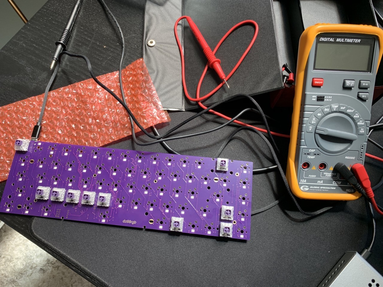
With the modifications above, I was able to build a version of the QMK firmware that added my own custom keybinding to toggle a specific pin on my keyboard on and off, using the backlight functionality. I used a multimeter to validate pin A1 was off by default, and after pressing the backlight toggle key, I measured that pin A1 indeed turned on. Success!
Dimmable Underglow
Finding Dimmable (PWM) Pins
In order to dim LEDs, we need to connect them to PWM ports. Since the PCB I have conveniently breaks out pins A1-A5, I took a look at which of those pins can be controlled by PWM. From page 47 of the spec I found the STM32F303 has alternate functions for the breakout pins which allow them to function as PWM pins, with the following mapping:
| Pin | Timer |
|---|---|
| PA1 | TIM2_CH2 or the TIM15_CH1N (The inverse or “not” of TIM15_CH1) |
| PA2 | TIM2_CH3 or TIM15_CH1 |
| PA3 | TIM2_CH4 or TIM15_CH2 |
| PA4 | TIM3_CH2 |
| PA5 | TIM2_CH1_ETR (this stands for external trigger, and is an input for a signal to trigger TIM2) |
I’m in luck that virtually every pin broken out on my PCB has PWM capabilities! We could approach this a number of ways, but since these pins have high power output according to the spec, I decided to use a single pin to directly drive the 4 LEDs I’ll be connecting. TIM2 is a 32 bit timer and TIM3 is a 16 bit timer (according to Section 3.17 on Page 23), both of which are totally overkill for LED dimming, but let’s use what we have. TIM15 is not referenced in the QMK or ChibiOS config files, so I avoided using this timer. I later found out that TIM2 was already used for another feature (more on this later). So I settled on using Pin A4, configured as Timer 3 Channel 2. According to the spec, to use Pin A4 as TIM3_CH2 we need to initialize it with “Alternate Function 2”, so let’s take a look at how to initialize the pin.
Writing PWM Code
I’d like to give credit to jmdaly who I believe authored the co60 backlighting code that I used for reference when writing this backlighting code.
Below is the initialization code:
static PWMConfig pwmCFG = {
  0xFFFF,                               // PWM clock frequency
  256,                                  // PWM period (in ticks) 1S (1/10kHz=0.1mS 0.1ms*10000 ticks=1S)
  NULL,                                 // No Callback
  {
      {PWM_OUTPUT_DISABLED, NULL},
      {PWM_OUTPUT_ACTIVE_HIGH, NULL},   // Enable Channel 2
      {PWM_OUTPUT_DISABLED, NULL},
      {PWM_OUTPUT_DISABLED, NULL}
  },
  0,                                    // HW dependent
  0
};

void backlight_init_ports(void) {
  palSetPadMode(GPIOA, 4, PAL_MODE_ALTERNATE(2));   // Initialize pin A4 in alt mode 2
  pwmStart(&PWMD3, &pwmCFG);                        // Start the PWM driver on timer 3 using the PWM config
  backlight_set(0);                                 // Initialize the backlights to "off"
}
The line palSetPadMode(GPIOA, 4, PAL_MODE_ALTERNATE(2)); specifically initializes the pin in the mode necessary to access the timer. The line pwmStart(&PWMD3, &pwmCFG); starts the corresponding timer. Note the pwmCFG configuration which defines the duty cycle, and importantly also specifically activates channel 2 for this timer.
Next, let’s look at how to set the levels. If you are familiar with Arduino programming, this is the same behavior as analogWrite().
static uint16_t cie_lightness(uint16_t v) {
  if (v <= 5243) // if below 8% of max
    return v / 9; // same as dividing by 900%
  else {
    uint32_t y = (((uint32_t) v + 10486) << 8) / (10486 + 0xFFFFUL); // add 16% of max and compare
    // to get a useful result with integer division, we shift left in the expression above
    // and revert what we've done again after squaring.
    y = y * y * y >> 8;
    if (y > 0xFFFFUL) // prevent overflow
      return 0xFFFFU;
    else
      return (uint16_t) y;
  }
}

void backlight_set(uint8_t level) {
  uint32_t duty = (uint32_t)(cie_lightness(0xFFFF * (uint32_t) level / BACKLIGHT_LEVELS));
  if (level == 0) {
      // Turn backlight off
      // Disable channel 2 on PWM3
      pwmDisableChannel(&PWMD3, 1);
  } else {
    // Turn backlight on
    // Enable channel 2 on PWM3
    pwmEnableChannel(&PWMD3, 1, PWM_FRACTION_TO_WIDTH(&PWMD3,0xFFFF,duty));
  }
}
Now let’s enable PWM through configs.
Default configs are stored in ...\qmk_firmware\quantum\stm32. Copy mcuconf.h and halconf.h into the directory for your keyboard, e.g. ...\qmk_firmware\keyboards\dztech\dz65rgb.
In halconf.h, set the following: #define HAL_USE_PWM TRUE.
There are now errors about TIM2 also being used for ST. This is why I didn’t use the other pins that ran off of TIM2.
In mcuconf.h, set the following: #define STM32_PWM_USE_TIM2 FALSE. What’s important here is that TIM3 is used for PWM, which is set by the following: #define STM32_PWM_USE_TIM3 TRUE.
Binding the Backlight Functionality to Keys
Now we can set the additional backlight functionality in a custom keymap so we can control the backlight! The Getting Started Guide describes how to do this. Navigate to the keymaps folder (in my case this was ...\qmk_firmware\keyboards\dztech\dz65rgb\keymaps). I created a copy of the default folder so I could customize the keymap, and named it halogenica. From the QMK Backlight Feature page you can find the following table of related special commands to reference in keymap.c.
| Key | Function |
|---|---|
| BL_TOGG | Turn the backlight on or off |
| BL_STEP | Cycle through backlight levels |
| BL_ON | Set the backlight to max brightness |
| BL_OFF | Turn the backlight off |
| BL_INC | Increase the backlight level |
| BL_DEC | Decrease the backlight level |
| BL_BRTG | Toggle backlight breathing |
You can also see from the following keymap code that I bound most of the backlight keys to Row 2 (so you press Fn+Z to toggle, etc.)
const uint16_t PROGMEM keymaps[][MATRIX_ROWS][MATRIX_COLS] = {
        [_LAYER0] = LAYOUT_65_ansi( /* Base */
            KC_GESC,  KC_1,     KC_2,     KC_3,     KC_4,     KC_5,     KC_6,     KC_7,     KC_8,     KC_9,     KC_0,     KC_MINS,  KC_EQL,   KC_BSPC,    KC_GRAVE,\
            KC_TAB,   KC_Q,     KC_W,     KC_E,     KC_R,     KC_T,     KC_Y,     KC_U,     KC_I,     KC_O,     KC_P,     KC_LBRC,  KC_RBRC,  KC_BSLASH,  KC_DELETE,\
            KC_CAPS,  KC_A,     KC_S,     KC_D,     KC_F,     KC_G,     KC_H,     KC_J,     KC_K,     KC_L,     KC_SCLN,  KC_QUOT,            KC_ENT,     KC_PSCREEN,\
            KC_LSFT,  KC_Z,     KC_X,     KC_C,     KC_V,     KC_B,     KC_N,     KC_M,     KC_COMM,  KC_DOT,   KC_SLSH,  KC_RSFT,            KC_UP,      KC_PAUSE,\
            KC_LCTL,  KC_LGUI,  KC_LALT,                      KC_SPC,                       KC_RALT,  MO(1),    KC_RCTL,  KC_LEFT,            KC_DOWN,    KC_RIGHT),
        [_LAYER1] = LAYOUT_65_ansi( /* FN */
            KC_GESC,  KC_F1,    KC_F2,    KC_F3,    KC_F4,    KC_F5,    KC_F6,    KC_F7,    KC_F8,    KC_F9,    KC_F10,   KC_F11,   KC_F12,   KC_DEL,     KC_HOME,\
            KC_TRNS,  RGB_TOG,  RGB_MOD,  RGB_HUI,  RGB_HUD,  RGB_SAI,  RGB_SAD,  RGB_VAI,  RGB_VAD,  KC_TRNS,  KC_PSCR,  KC_SLCK,  KC_PAUS,  RESET,      KC_PGUP,\
            KC_CAPS,  RGB_SPI,  RGB_SPD,  KC_TRNS,  KC_TRNS,  KC_TRNS,  KC_TRNS,  KC_TRNS,  KC_TRNS,  KC_TRNS,  KC_TRNS,  KC_TRNS,            EEP_RST,    KC_PGDN,\
            KC_LSFT,  BL_TOGG,  BL_OFF,   BL_ON,    BL_DEC,   BL_INC,   KC_TRNS,  KC_TRNS,  KC_TRNS,  KC_TRNS,  KC_TRNS,  KC_TRNS,            KC_VOLU,    KC_MUTE,\
            KC_TRNS,  KC_TRNS,  KC_TRNS,                      KC_TRNS,                      KC_TRNS,  KC_TRNS,  KC_TRNS,  KC_MPRV,            KC_VOLD,    KC_MNXT),
};
Finally, you can use make dztech\dz65rgb:halogenica (or whatever your custom keymap name is) to buid the new firmware, and you can flash it with the QMK Toolbox just as before, being sure to select your new custom .bin file. For a full list of all code changes I’ve made, take a look at my github branch of QMK Firmware.
LEDs
The TADA68 has 4 small surface mount white LEDs for underglow; 2 on the left and 2 on the right side of the keyboard. My initial intent was to replace these LEDs and mount them internally. After some experimentation, I ended up switching to a different type of LED mounted externally, for a brighter and more uniform distribution of light. Let’s walk through the different LED options that might best suit your application.
LED Underglow Properties
The LEDs I rigged up have a few properties in common. Firstly, because the microcontroller in my keyboard operates on 3.3V and I’m driving the LEDs from there, the LED circuit needs to be rated for 3.3V. I also decided to use a single color, not RGB LEDs. It should be possible to use an RGB LED, but since I knew I wanted a single color this simplified the number of pins needed to control the LED and I no longer have to worry about a protocol to choose a color. I also knew I did not need to make the LEDs individually addressible, so they will all be controlled uniformally; they will all share the exact same brightness level. This means that I should be able to use a single pin from the microcontroller to control all LEDs used for underglow.
LED Power
As I mentioned above, the LEDs are all tied to a single high power and the PWM code is only controlling that single pin. This means that the LEDs share the power output of that single channel from the microcontroller. If the LEDs are not bright enough for your application, perhaps the best way to get more power is to use a transistor as a switch and tap into the USB power directly. That is beyond the scope of this post, but fortunately I’ll be writing another post on how to do this soon!
I highly suggest using a multimeter to verify the voltage output of where you are wiring your LEDs. You can also verify the current that the pin can deliver. In my case, I observed 20mA at ~3.9V. This is an important measurement because the voltage does not strictly match the voltage advertised, and it can be helpful to understand the available power delivery when selecting LEDs so you can predict the potential brightness. In my case, I had several LEDs available on hand and I was able to experiment with different resistor values to get the right brightness and power levels, but it’s always best to measure and verify.
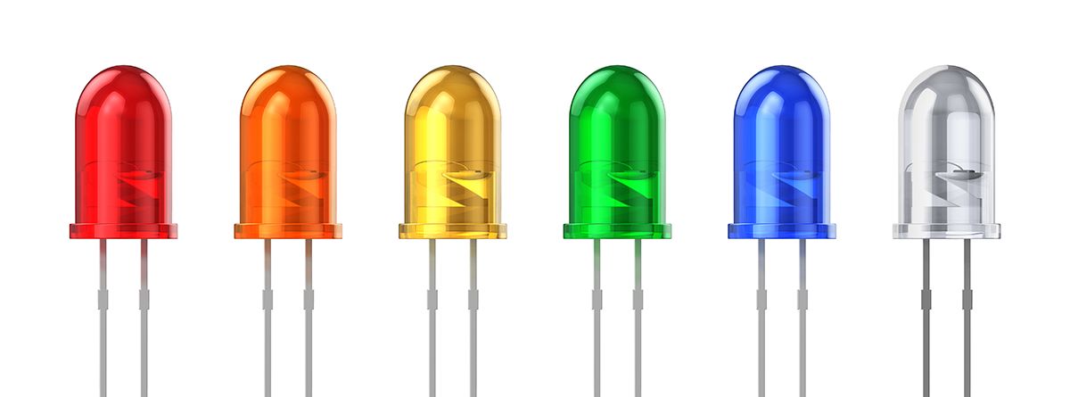
Traditional LEDs
These LED are common in through hole applications and hobbiest electronics. However they are fairly large and awkward to mount on a flat surface with no through holes. Also because they’re so directional (as all LEDs are), I was concerned that the brightness and light pattern would not be uniform if I wasn’t able to get all the LEDs perfectly mounted. I decided to look for a different kind of LED that would be easier to mount.
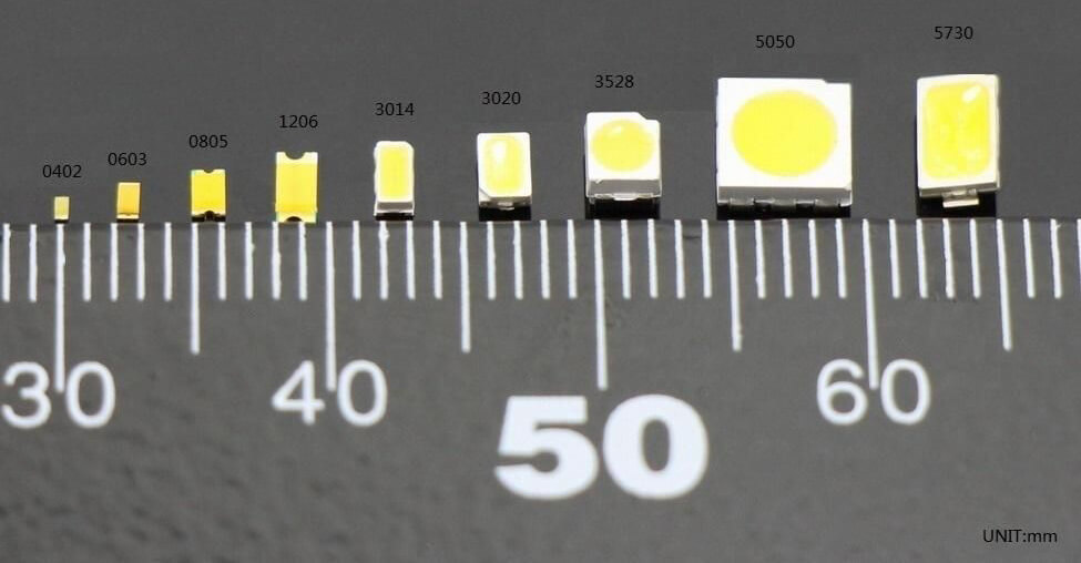
SMD LEDs
These LEDs use an SMD package (Surface Mount Devices) and are extremely small. They are available in a wide variety of colors, and can be ordered with resistors packaged in that enable connecting them directly to a power source at either ~3V or ~9V. They are also available pre-wired, or standalone which would require you to solder some extremely small wires on yourself. For this application, I would highly suggest getting the pre-wired kind of LEDs because it can be difficult to properly solder wires onto SMDs this small unless you’re an experienced solderer. I purchased mine pre-wired from Aliexpress.
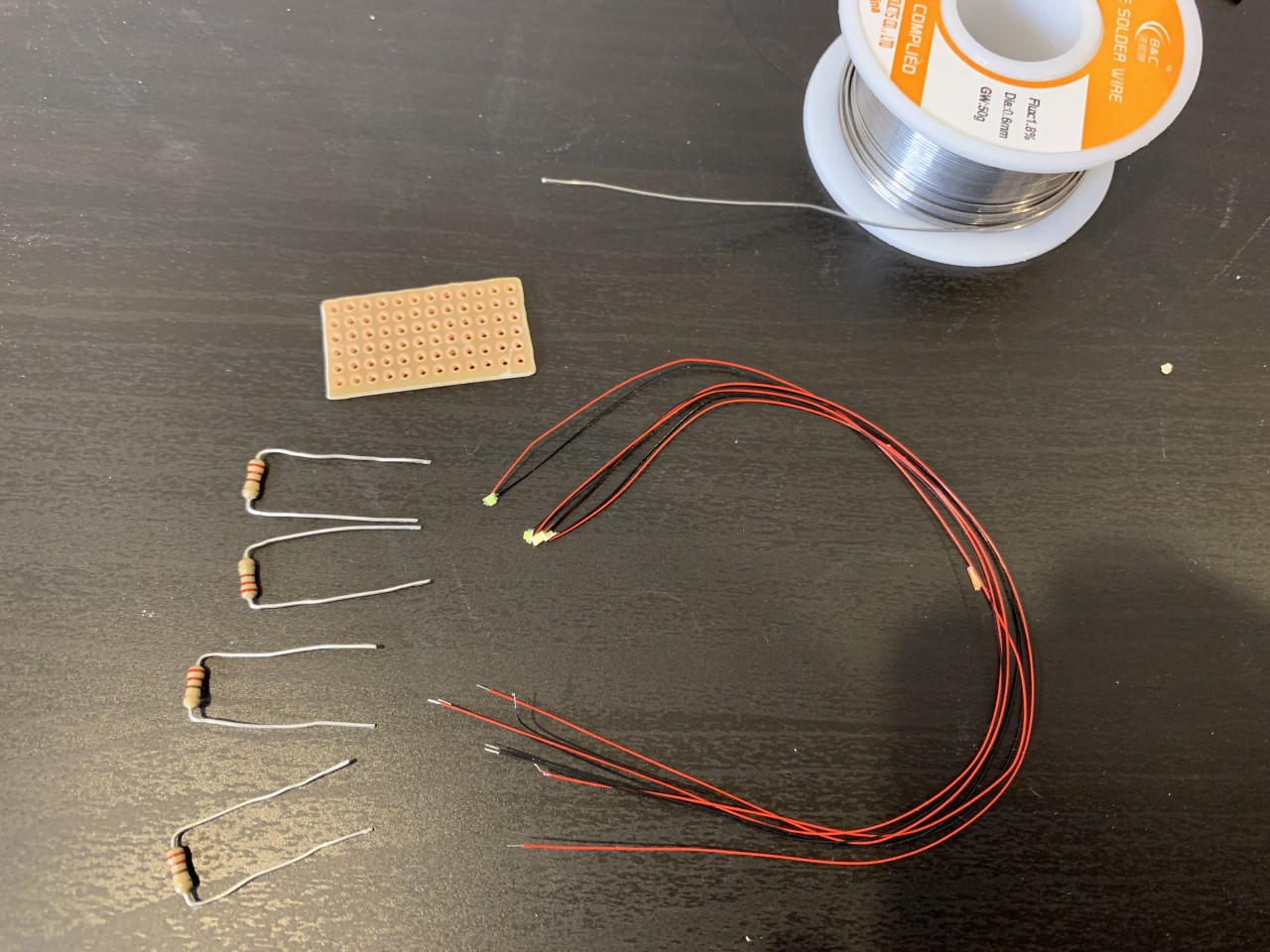
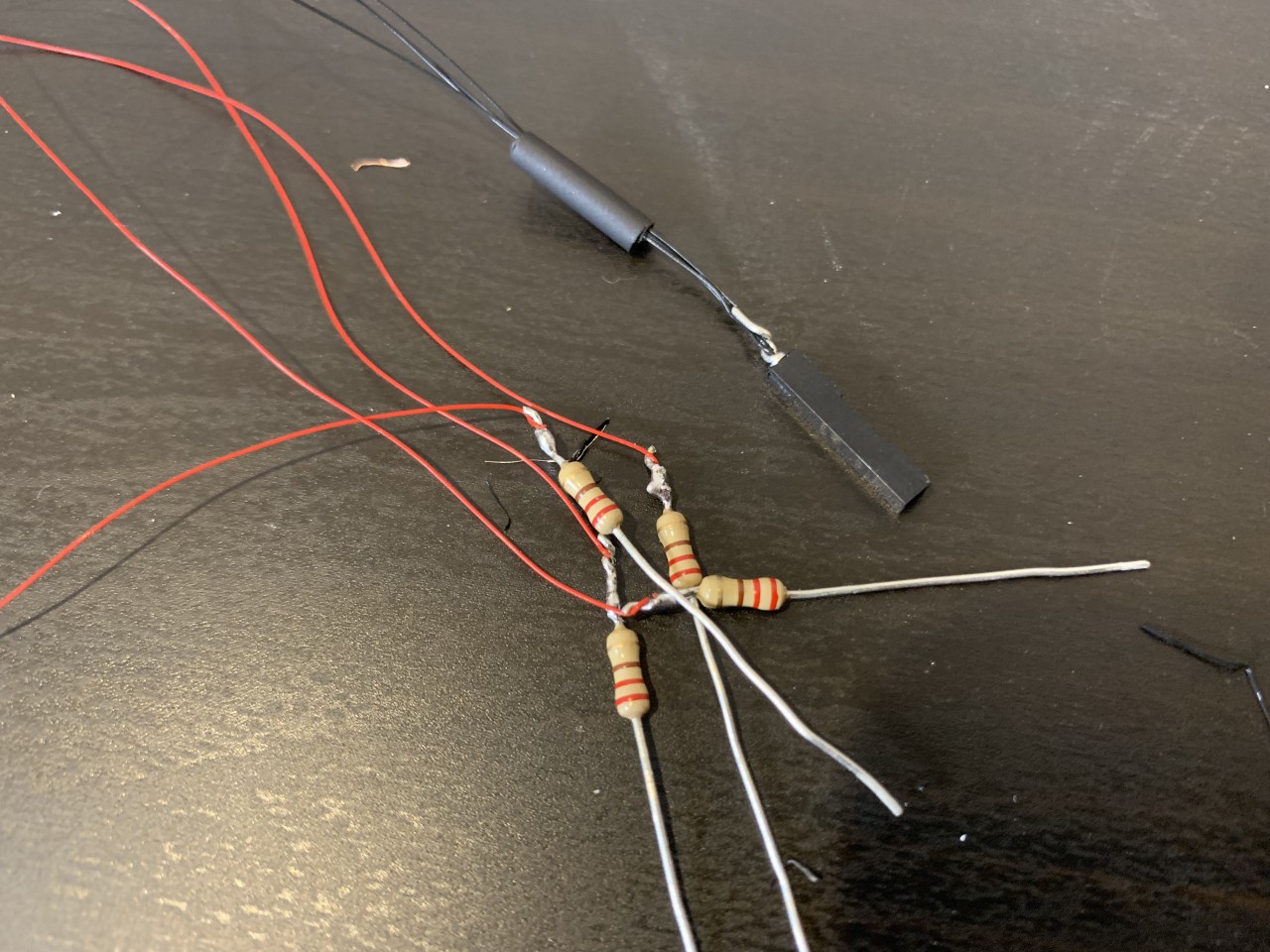
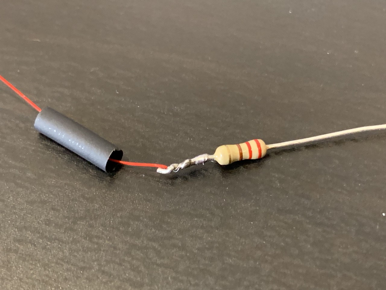
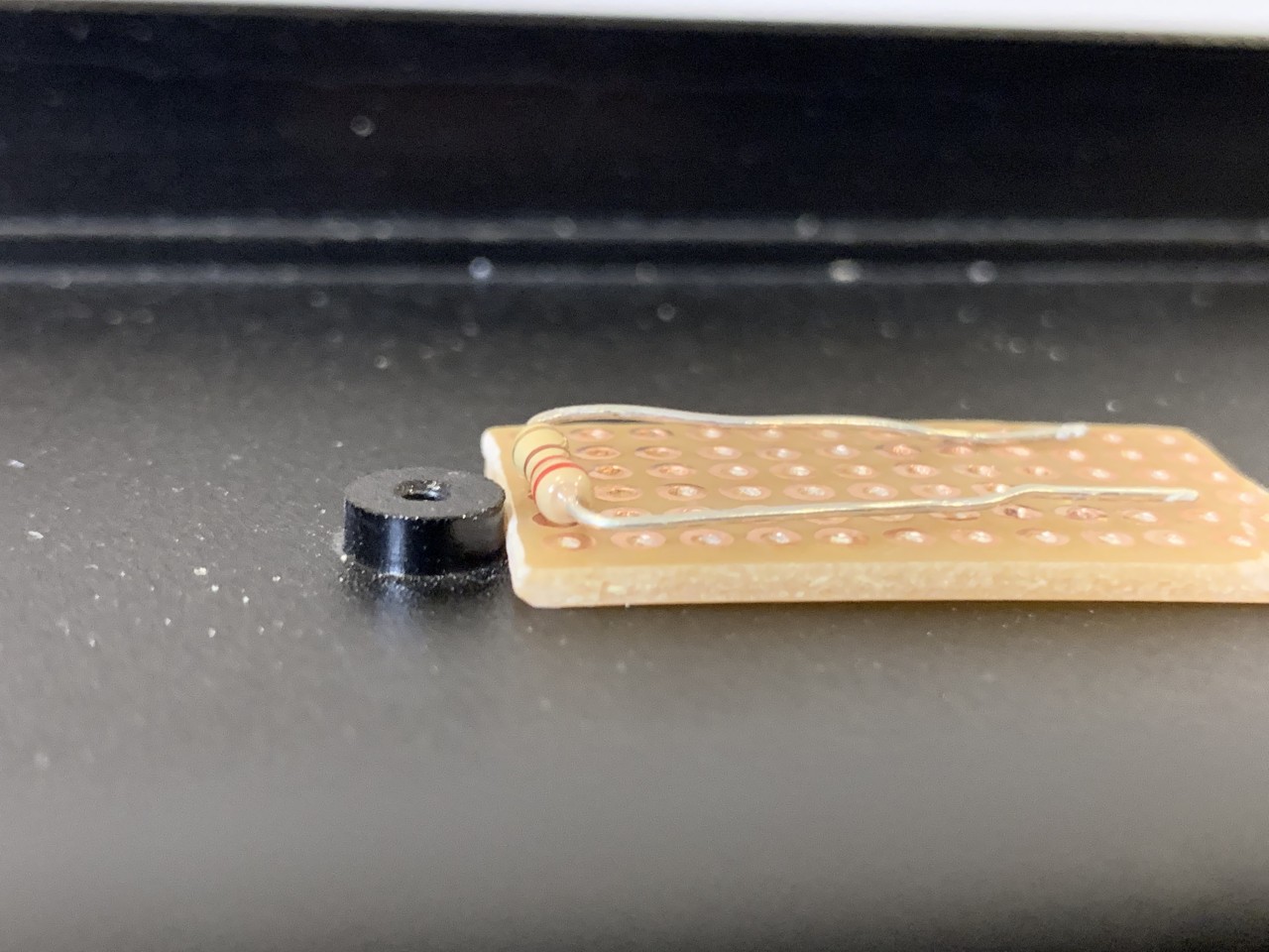
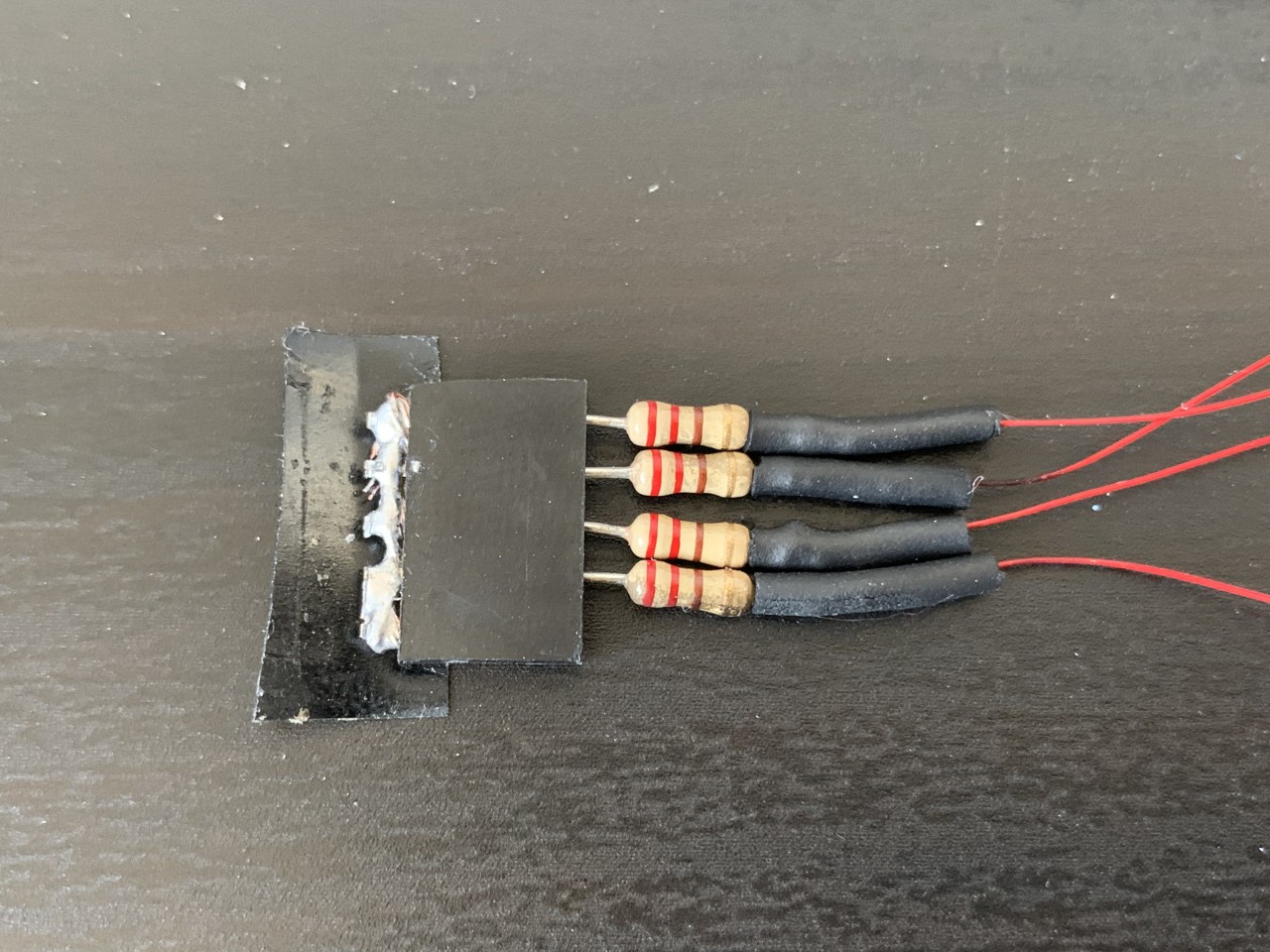
To create the circuit for these LEDs I chose to add resistors in line. This may not be strictly necessary, but I was trying to make a robust solution and I didn’t want the LEDs to burn out over time or for one LED to be brighter than another. This is also why I used a resistor for each individual LED instead of a single resistor for all LEDs. All electrical components can vary slightly, and even LEDs from the same batch may have a different internal voltage drop. Current will follow the path of least resistance, so if one of the LEDs has a slightly lower operating power (aka Voltage Threshold), it’s possible a majority or all of the current will flow through that LED and the other LEDs will not turn on. To combat that, a resistor on each LED helps to normalize the resistance for each LED and get a more even power distribution, and therefore a more uniform brightness. You can find more information on StackExchange
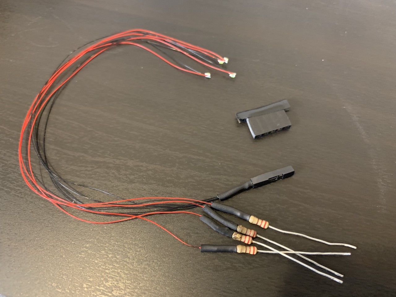
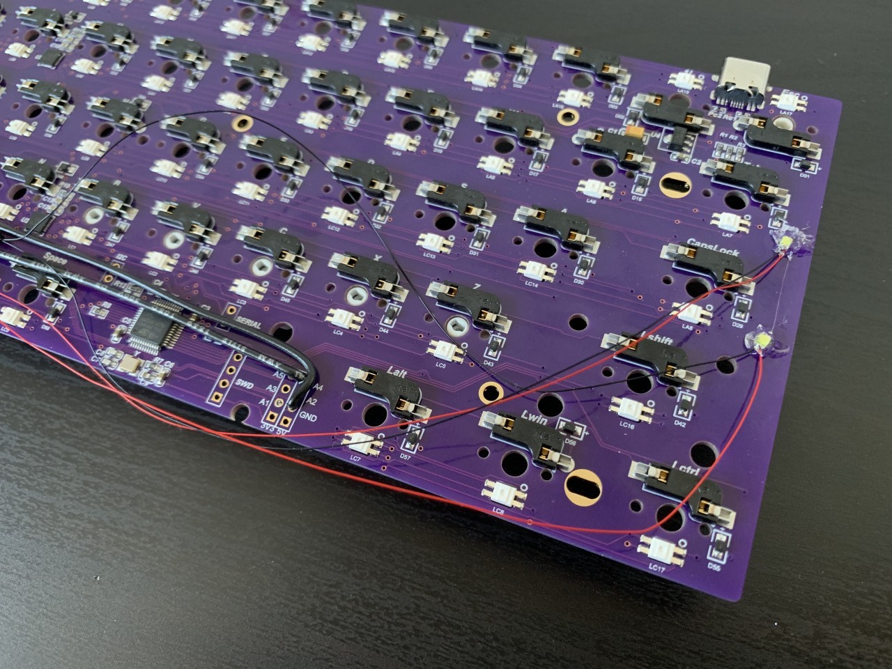
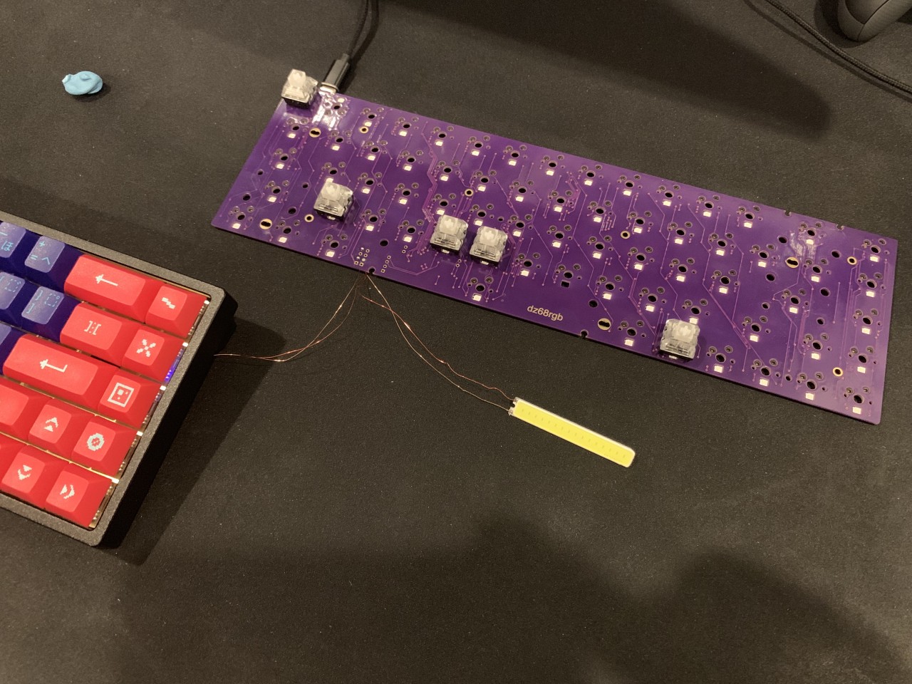
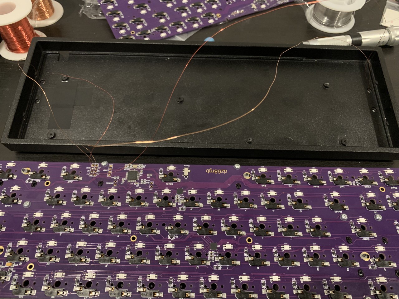
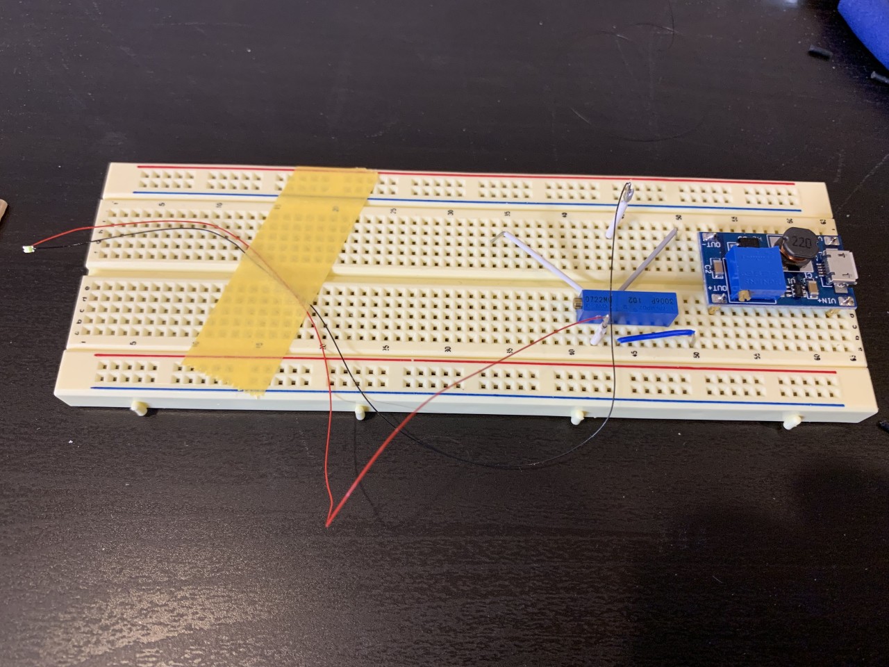
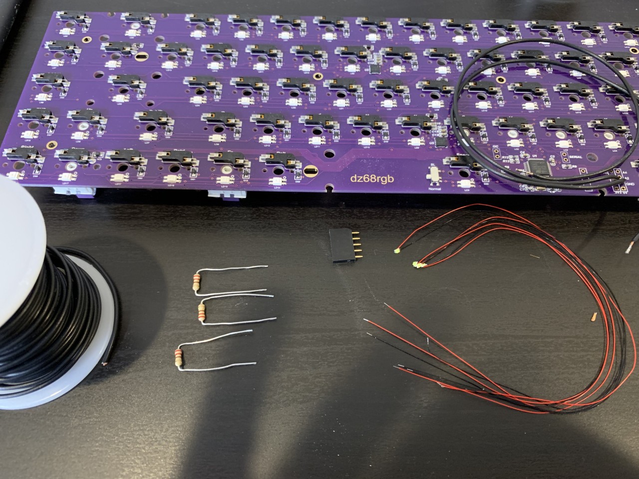
Below you can see the test circuit, and how I soldered the particularly thin wires to the LEDs. The smaller blue component in the test circuit is a potentiometer, which I can tune to different resistance values. I chose resistors of 220 Ohms. Using this circuit I was able to verify the brightness at a given operating voltage and current and choose the right resistors for the circuit. To create the final circuit I first tried to mount components to a small protoboard. However even the protoboard was so thick I was unable to fit it underneath the the PCB. Instead I decided to use some female headers that I shorted together to connect all the resistors to the circuit, which has the additional benefit of being removable. The ground for all the LEDs were tied together and another small female molex connector plugs into ground.
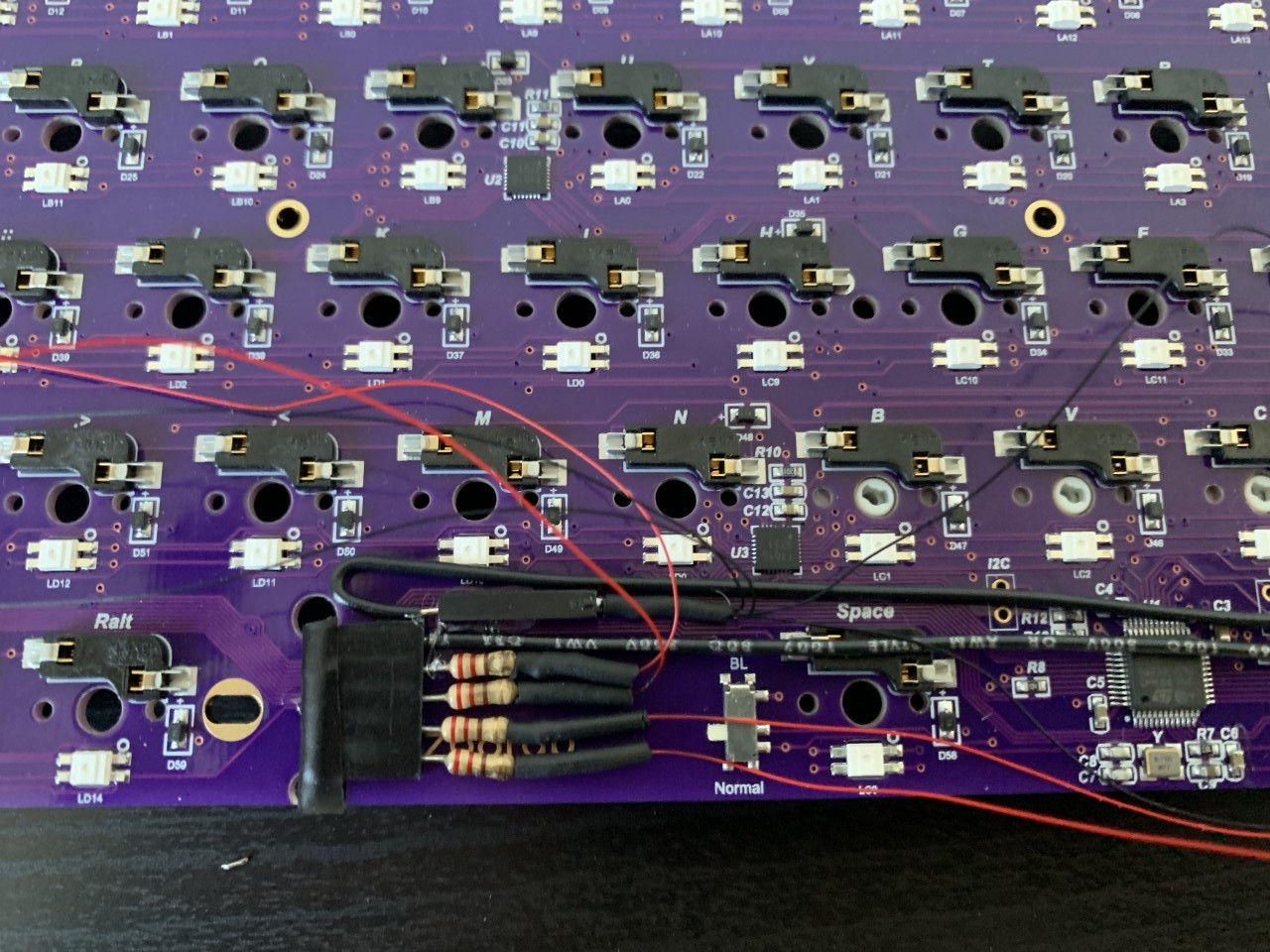
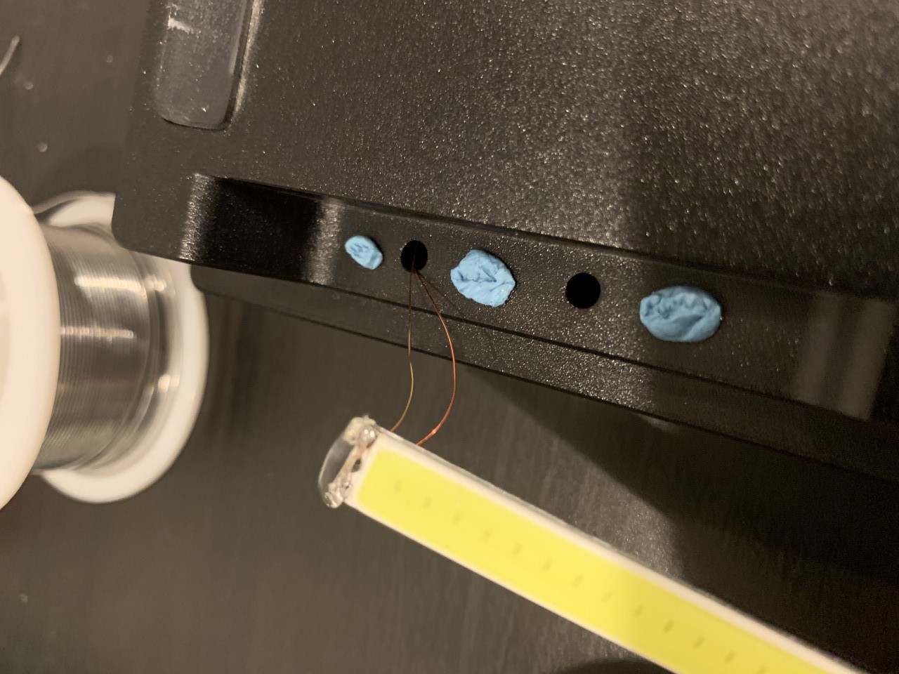
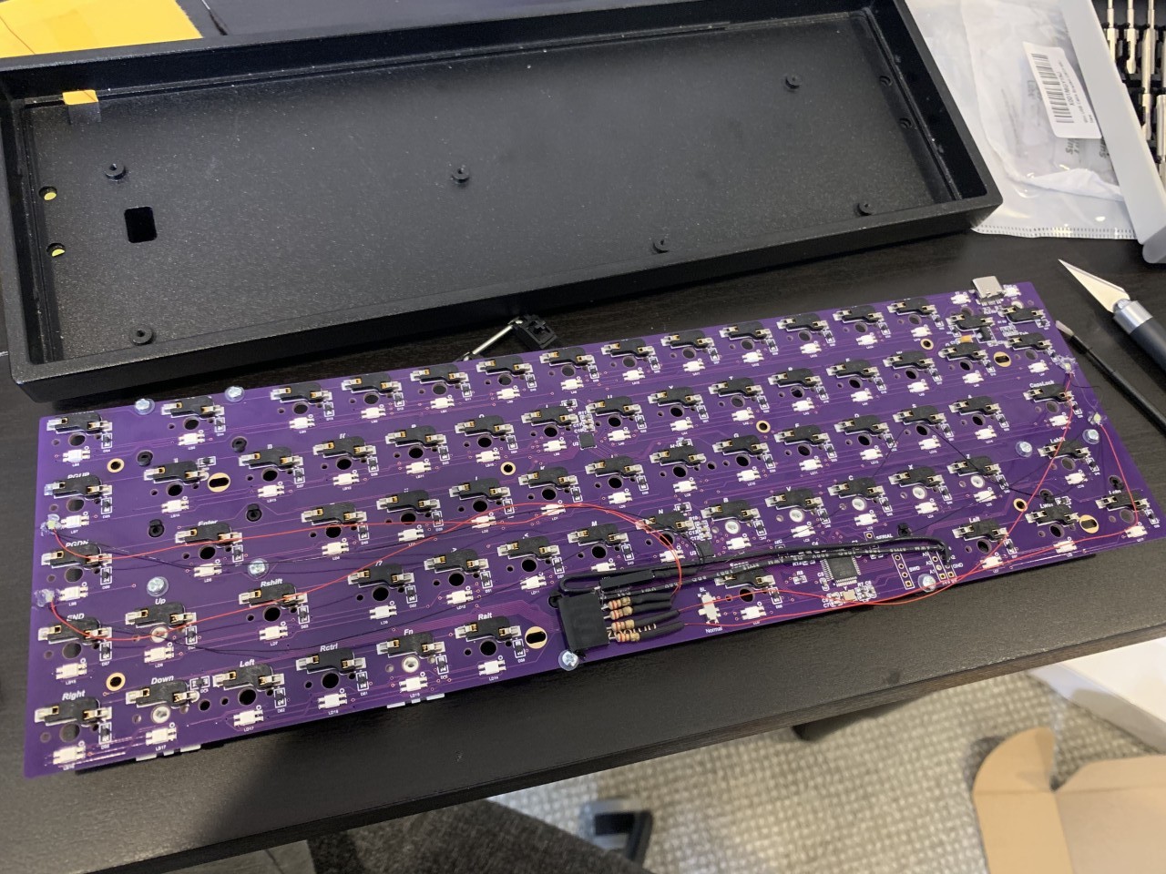
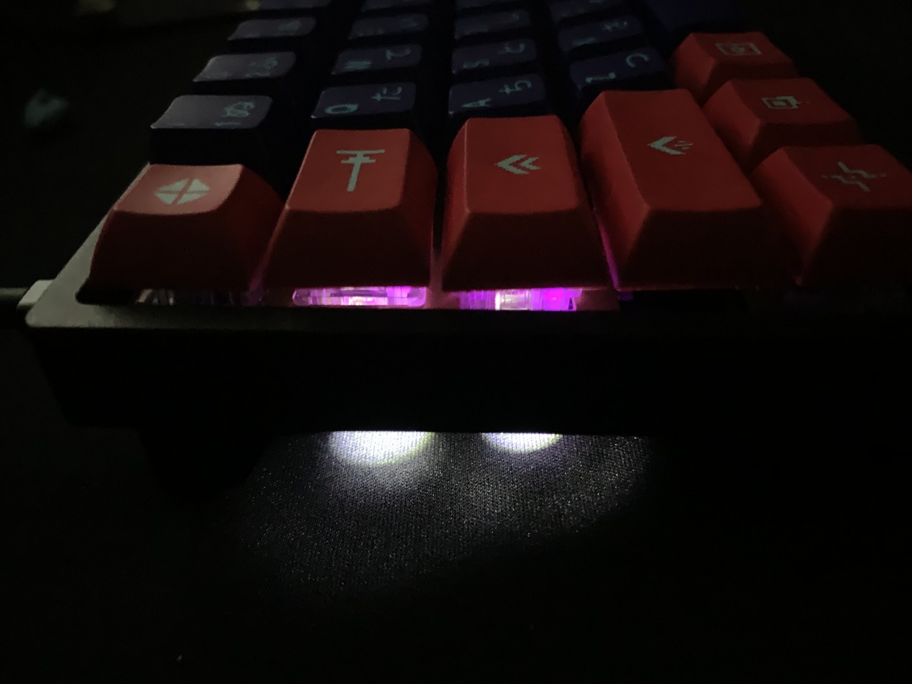
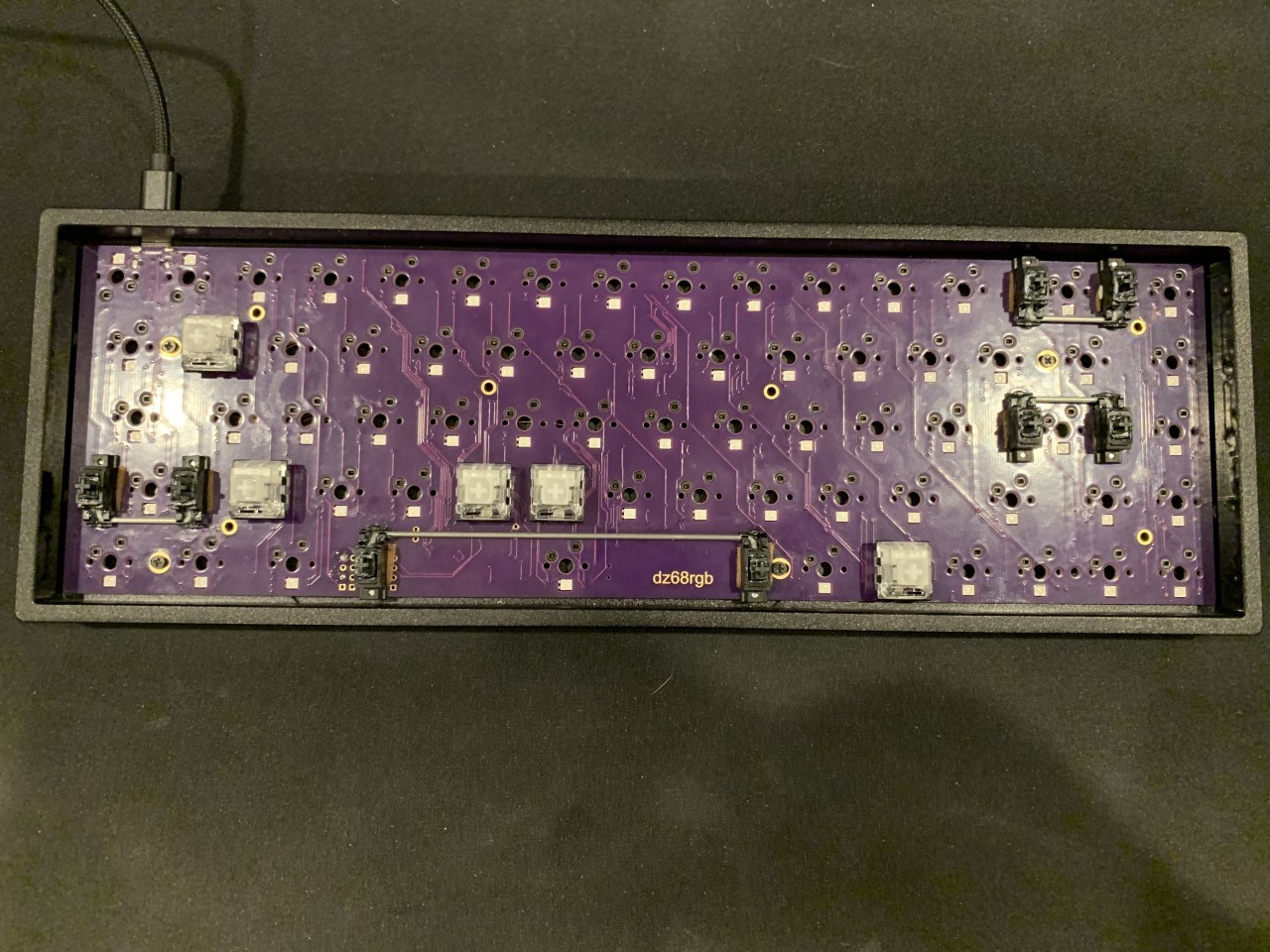
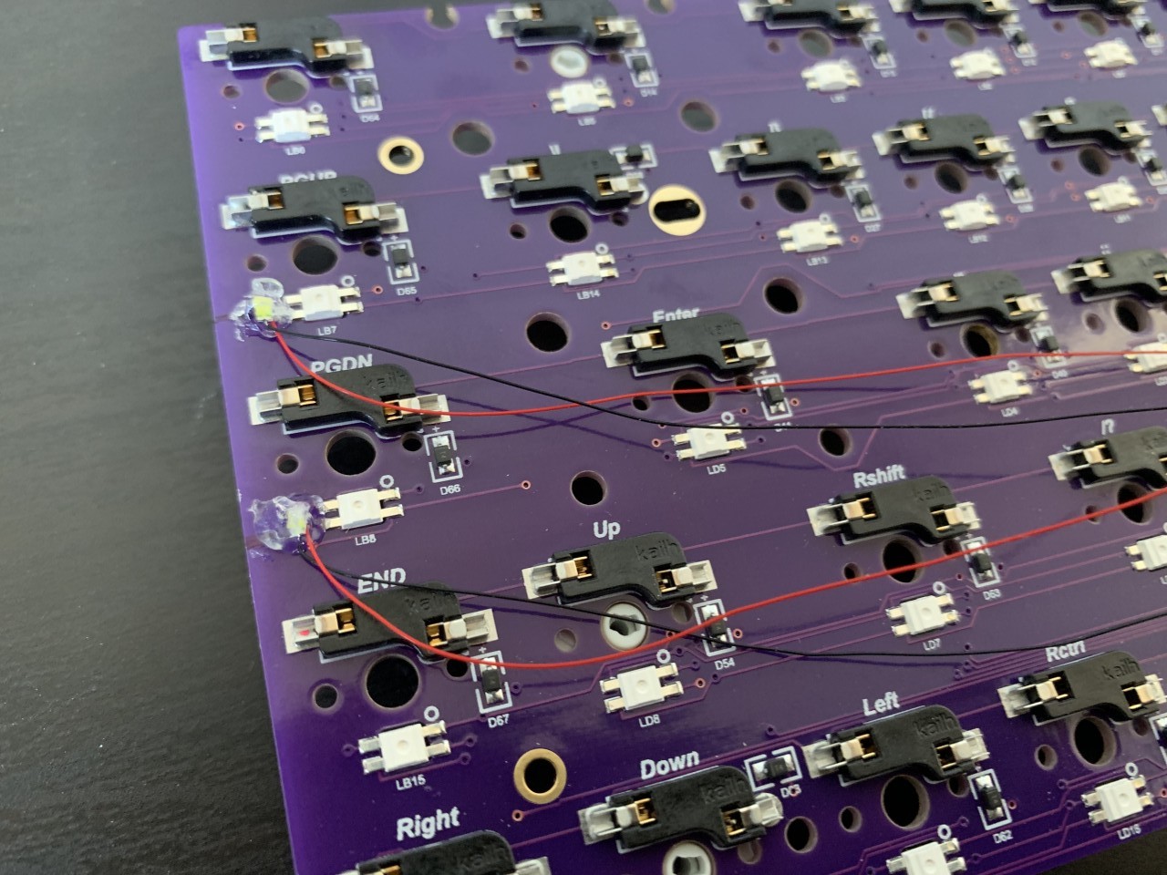
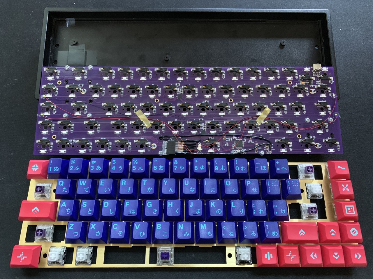
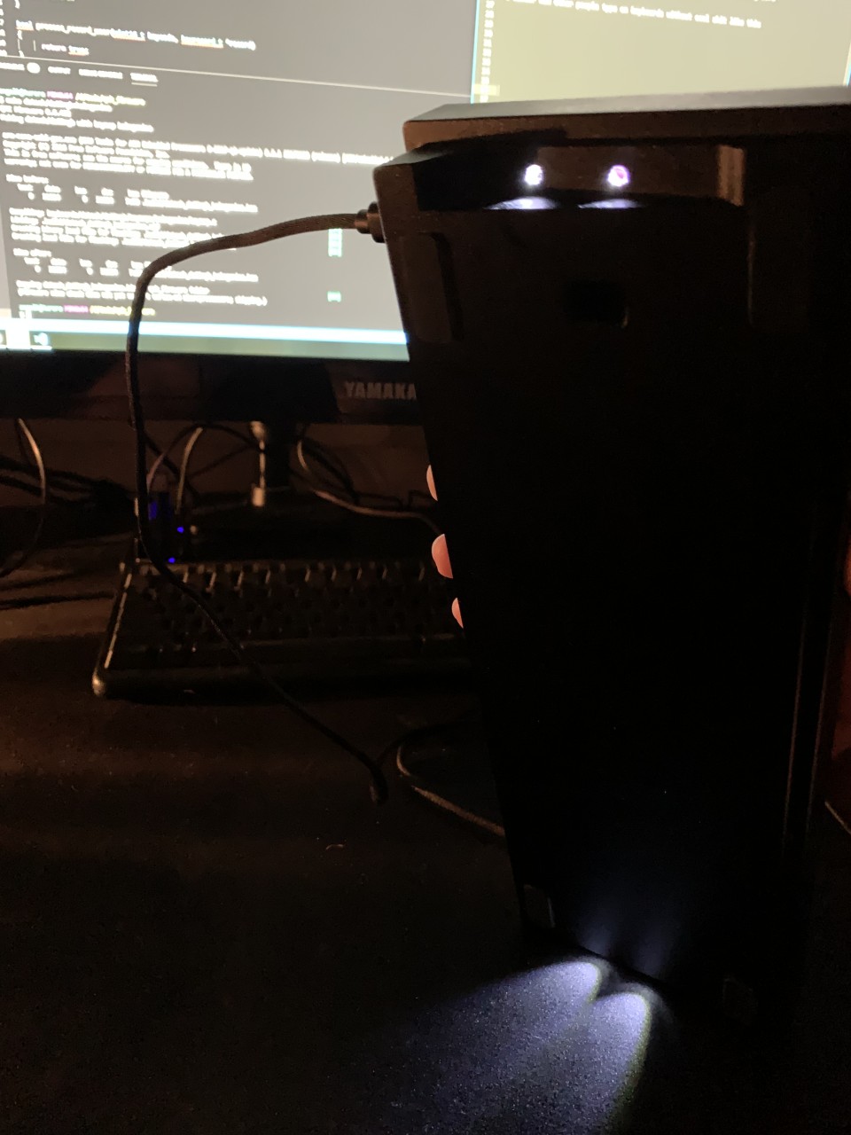
Finally, I assembeled everything. To align the LEDs with the holes in the TADA68 case, the LEDs actually need to be aligned on top of existing components on the PCB (which is presumably why this feature was omitted from the DZ65RGB in the first place). To mount the LEDs, one of the simplest and most effective methods is simply hot glue. Most hot glue does not conduct electricity when cured, and therefore it can be used on top of existing components. It is cleanly removable if necessary, but strong enough to hold small LEDs in place. The trickiest part is getting a dab of glue in exactly the right spot, and getting the LED seated in the glue pointing in the right direction before it dries and hardens. To do this, I held the LED with tweezers in one hand, the glue gun in the other hand, and worked very quickly to mount them in under 10 seconds. Thankfully no harm is done if you don’t get it right the first shot, it’s very easy to peel the glue off and try again. I also wanted to make sure I didn’t pinch any of the wires underneath the PCB, so I taped them in place out of the way. At first I tried electrical tape but it simply didn’t hold. I then switched to masking tape which worked wonderfuly. The fully assembled board is below. I was happy with the brightness, however I was not happy with the very direct light source - it was not softly diffused and did not cover much desk area. It was frankly difficult to see from my default seating position so I continued investigating LEDs…
COB LED
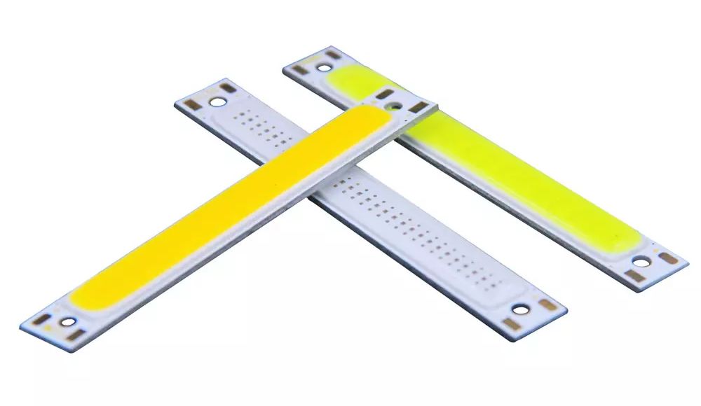
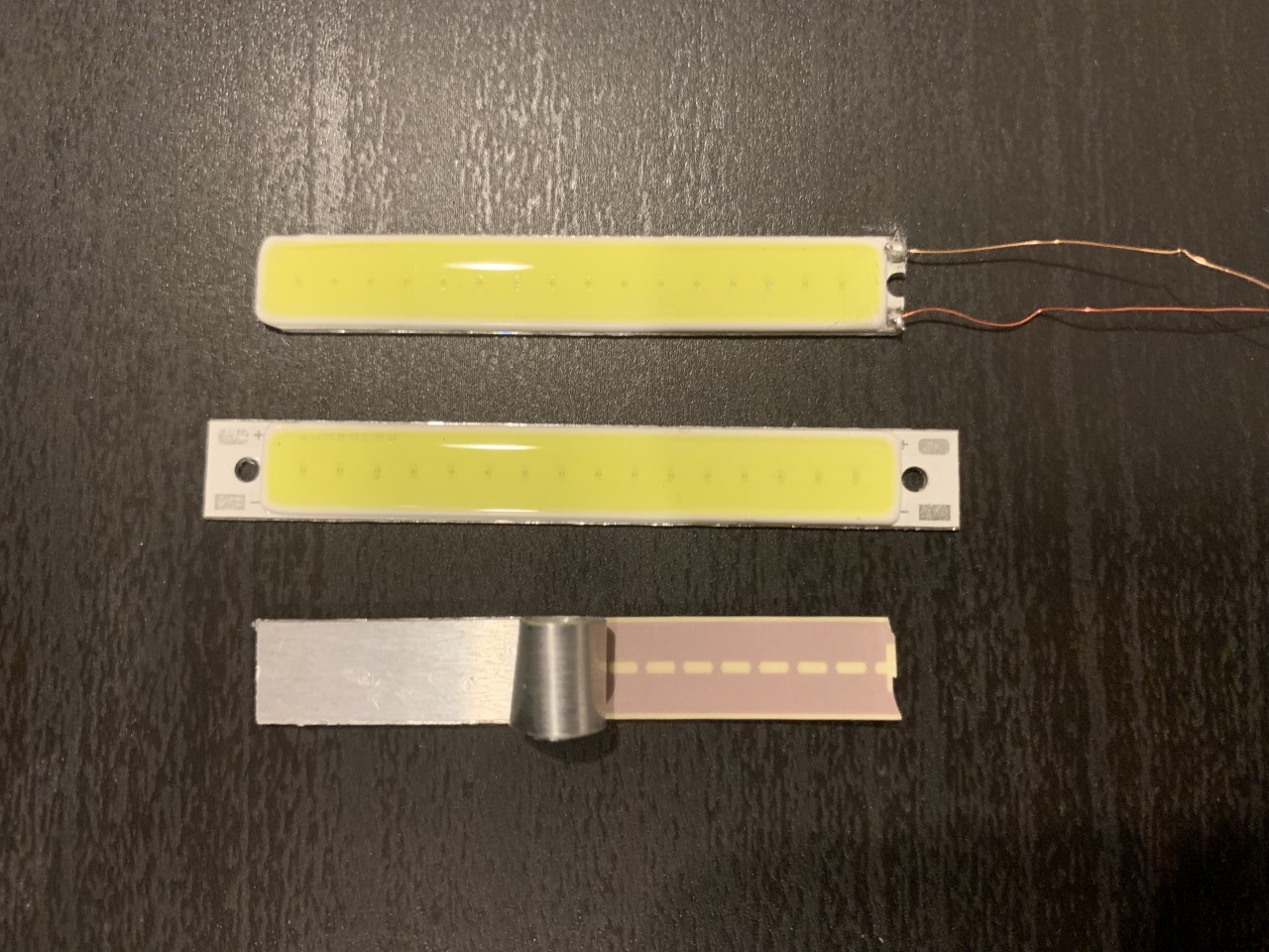
A recent LED invention is the COB LED, which stands for “Chip On Board” LED. Normally, an LED behaves like a single point light source. To give the appearance of an area light source, like a bar of light, we used to use LED strips with a diffusing piece of plastic. However this adds bulk to the LED, and the diffusers can only do so much to make the light uniform. The COB LED is different - it actually has several diodes in a single substrate, and the entire substrate illuminates fairly uniformally. This allows more interesting shapes and less bulk. One possible downside is that they are not available in a huge variety of colors, and by far white was the most popular at the time I purchased. I expect it’s very possible to produce these LEDs in other colors, but they’re just significantly less common in the form factor I was looking for.
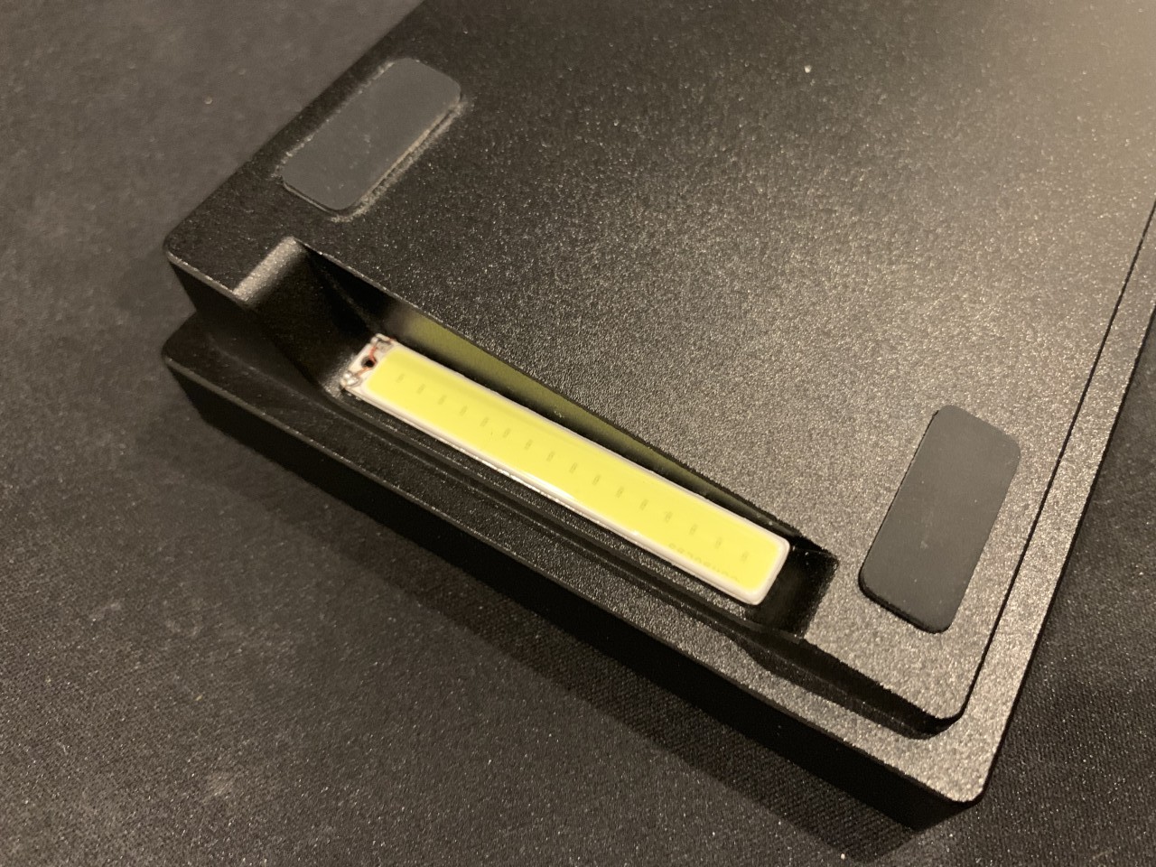
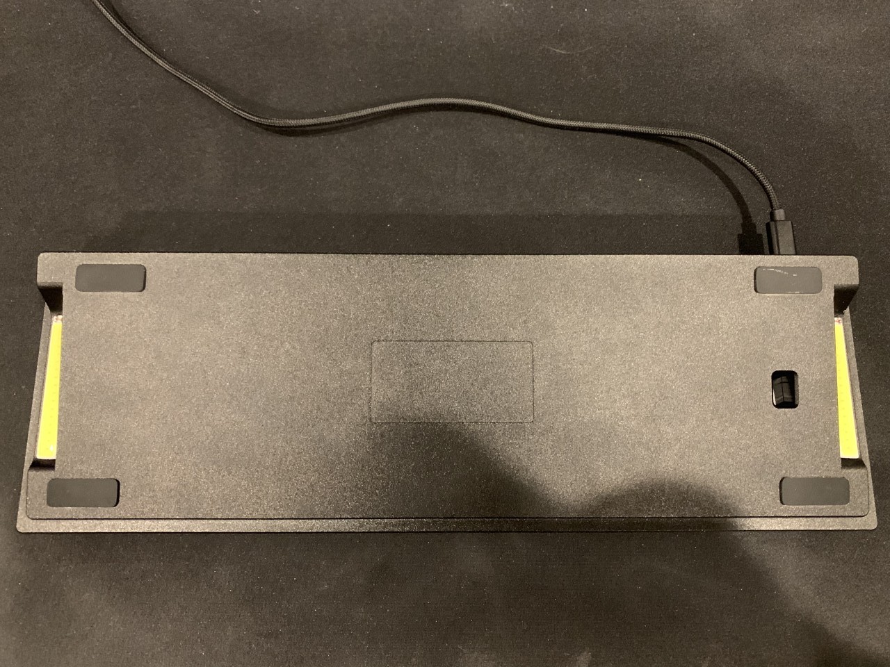
After researching, I found that there are several standard sizes that closely fit notches on the sides of the TADA68 case. The 50x7mm package appeared to fit perfectly but the substrate does not fill the package surface area and unfortunately it is designed to run at 9V which I was unable to drive with the keyboard. Another common size is 60x8mm, which thankfully works on 3.3V, but unfortunately appears just a few millimeters too long for the case. I decided to order several from Aliexpress (you can also find them on ebay, but I believe they’re all sourced from China) to experiment with them. I chose the 1W cool white version.
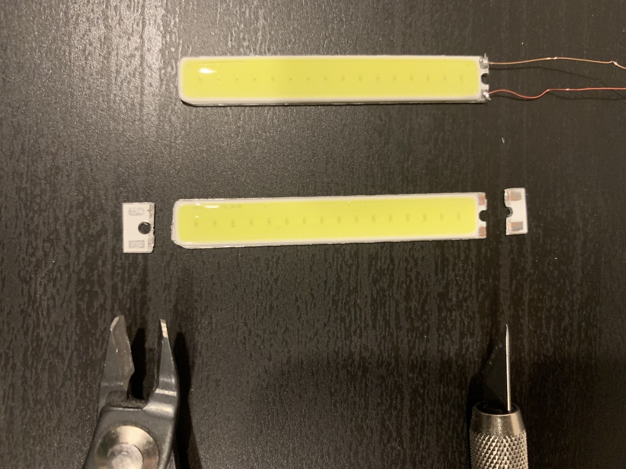
I first attempted using the 9v LEDs that would natrually fit my case. Unfortunately, I wasn’t able to get these to power with any significant brightness below 7V, so they were basically unusable. I then decided my best option would be to try to trim the 3.3V LEDs down to size. I carefully separated the layers of the LED with a pen knife, and peeled back the metal heatsink with some pliers. As you can see in the photos below, the yellow substrate is what emits a difuse light, the small dots inside are the actual diodes, and the copper tracks under the heatsink are the positive and negative lines. These copper lines actually run the whole length of the board, so it’s actually possible to trim the board to size as long as you don’t separate the yellow substrate from the board, and the LED will still be functional! I ended up trimming off the conductive pads, so to get to the copper lines I actually scraped the board away with a razor until the copper lines were exposed. I was able to then solder wires directly to these lines. I was using extremely thin 0.2mm magnet wire which is very finicky and did not make a good connection. After attempting a few different ways of trimming the LED, I finally chose to leave one of the mounting holes untrimmed and I wrapped the magnet wire through the hole and around the outside of the board a few times to hold the wire in place. I then soldered the whole coil in place which made a better connection and gave it more strength.
In this case I did not use resistors, and perhaps I should have. Since the COB LEDs actually have several LEDs in parallel in the package, it seemed less likely that the LEDs were in danger of being mismatched and producing non-uniform brightness. I had also wired these LEDs directly to a power source when testing and found them to be much brighter and consume much more power than I was able to produce from the output pin on my microcontroller. Therefore I didn’t think it was likely I would burn out the LED either. So in an effort to simplify everything, I just wired the LEDs directly to the pins on the PCB.
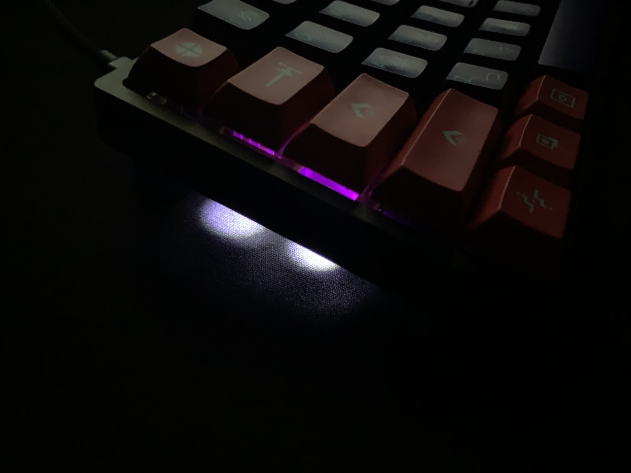
It was easy to run the thin magnet wires through the existing holes where the previous LEDs would shine through. However I was having trouble attaching the LED to the aluminum case. I first tried hot glue, but it had a very weak bond and it’s also difficult to make a totally clean bond with hot glue because it’s very stringy. A more permenant option would be epoxy, but I didn’t want to risk any permenant damage to my case in the event I wanted to switch LEDs later. Thankfully I found that blu tack (poster tack) worked extremely well! It made a very tight bond, it could be removed and cleaned without much trouble, and it is completely concealed under the LED.
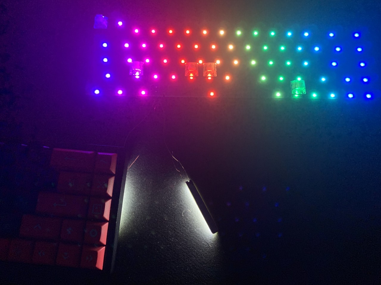
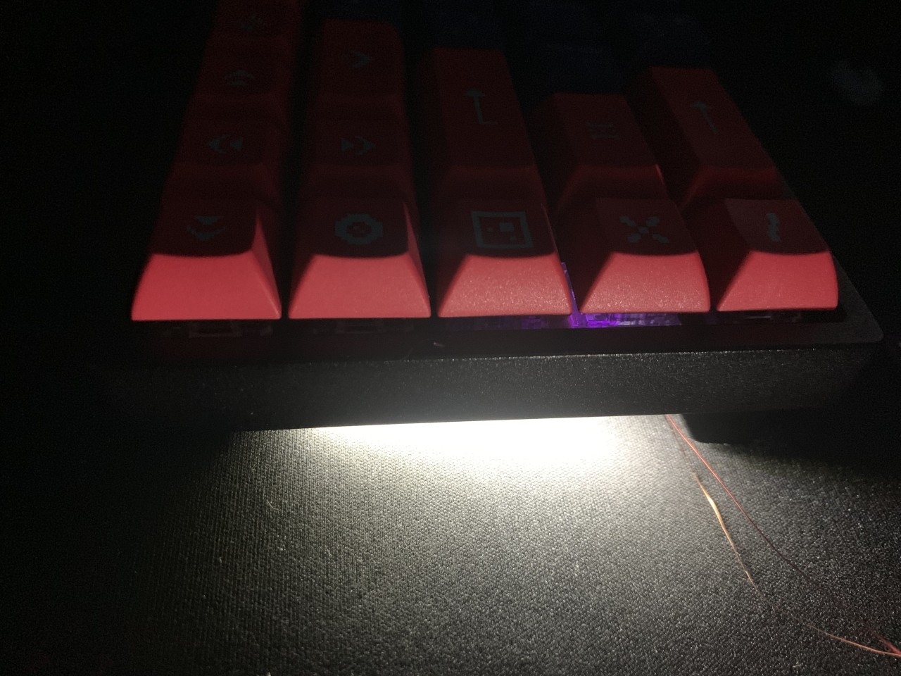
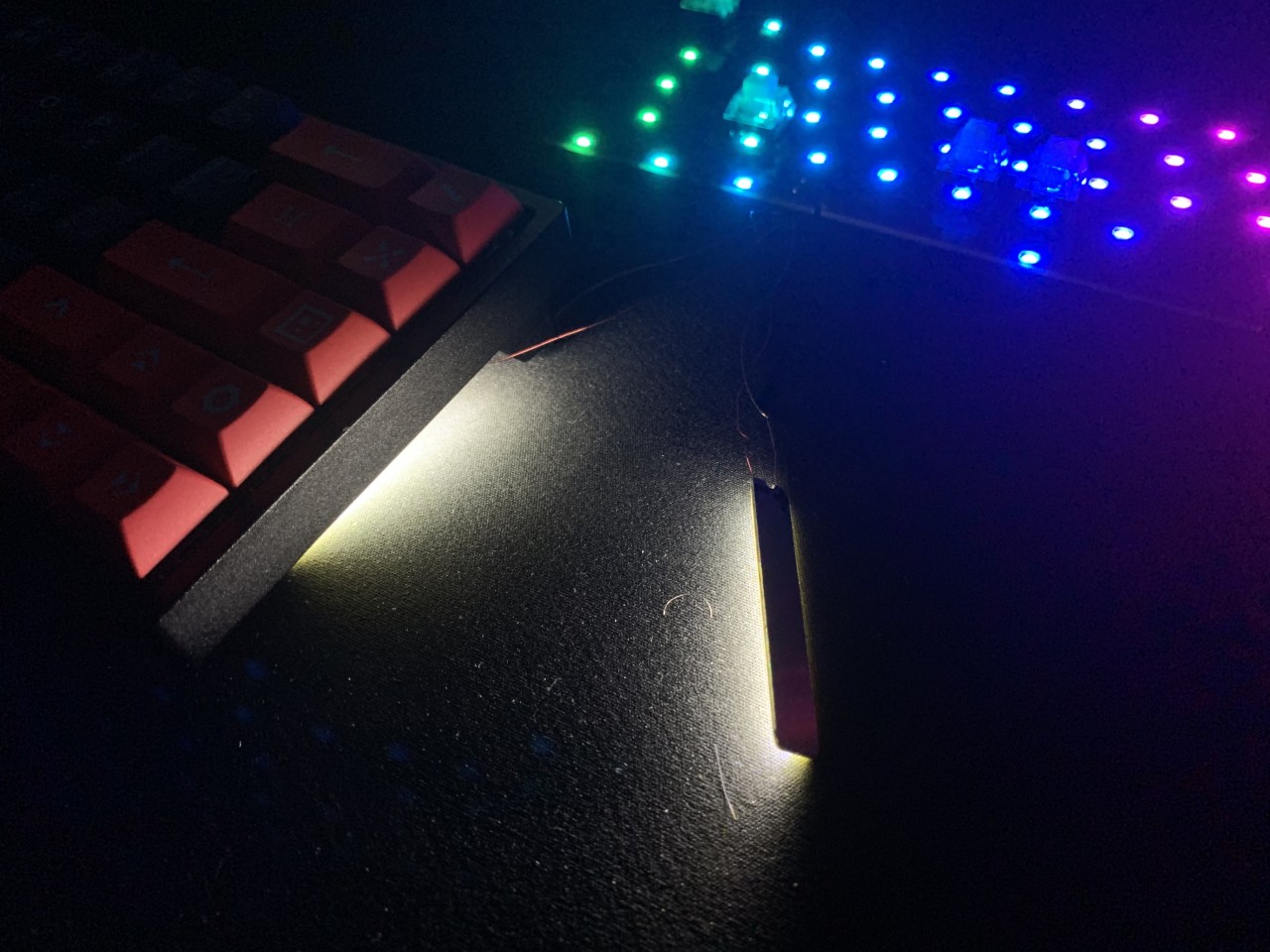
The final result was much brighter and much more uniform than the SMD LEDs. At full brightness, the underglow is extremely bright, and I tend to keep them between 20-40% brightness under normal use. They appear to dim uniformally, and don’t produce any noticable heat. Their mounting location is perfect, and they are essentially impossible to see unless looking underneath the keyboard. I’m extremely please with the results, and the final product looks professional and high quality.